


4. CONTROL UNIT CONNECTIONS
4.14 Connecting the IO Device with CC-Link
I - 41
4.14 Connecting the IO Device with CC-Link
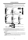
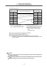
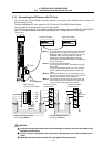
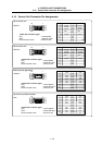
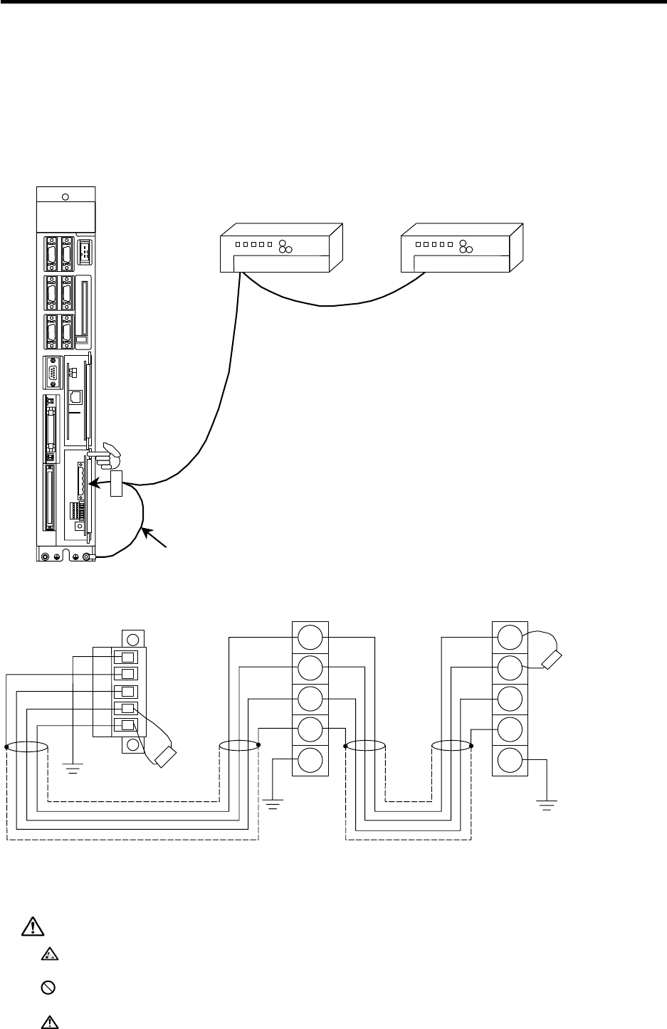
The CC-Link unit (FCU6-HR865) must be mounted in the control unit's extension slot to connect IO
devices using CC-Link.
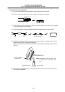
Connect a dedicated CC-Link cable to the CC-Link unit (FCU6-HR865) terminal block.
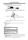
Always install the enclosed terminator on the final station.
This unit functions as the CC-Link system's master and local station. Refer to the MELSEC A1SJ61QBT11
type CC-Link System Master/Local Unit's User Manual, etc., for details on the CC-Link system.
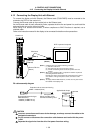
CC-Link
Remote I/O station
Terminal block
Terminato
r
(Note 2)
(Note 4)
(Note 1) The performance of the CC-Link system cannot be
guaranteed when a cable other than the CC-Link
dedicated cable is used. For details on the CC-Link
dedicated cable, refer to the CC-Link Partner
Association's web site (http://www.cc-link.org/).
(Information is provided in the section "Introduction
to Partner Makers".)
(Note 2) Use the enclosed terminator.
The terminator value differs according to the cable
being used.
The CC-Link dedicated cable uses 110Ω, and the
CC-Link dedicated high-performance cable uses
130Ω.
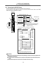
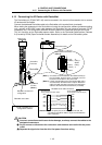
(Note 3) Connect the FG wire from the FG terminal on the
C64 control unit's CC-Link terminal block to the FG
terminal on the bottom of the control unit.
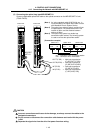
(Note 4) Pull out the CC-Link unit from the control unit and
set the C64 control unit's station No. setting rotary
switch and baud rate setting rotary switch.
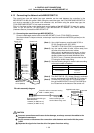
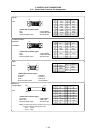
Control unit
C64 control unit
CC-Link terminal block
CC-Link
FG wire
(Note 3)
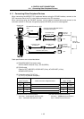
Shielded twisted pair cable
(3-core type)
(Note 1)
Shielded twisted pair cable
(3-core type)
(Note 1)
5 FG
4 SLD
3 DG
2 DB
1 DA
Terminato
r
(Note 2)
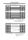
Remote I/O station
Remote I/O station
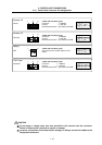
LED1
DA
FG
SLD
DG
DB
DA
FG
SLD
DG
DB
Remote I/O station
Terminal block
CAUTION
Incorrect connections could cause device damage, so always connect the cables to the
designated connectors.
Do not connect or disconnect the connection cable between each unit while the power
is ON.
Separate the signal wire from the drive line/power line when wiring.