


4. CONTROL UNIT CONNECTIONS
4.13 Connecting the Network with MELSECNET/10
I - 40
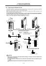
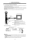
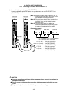
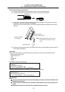
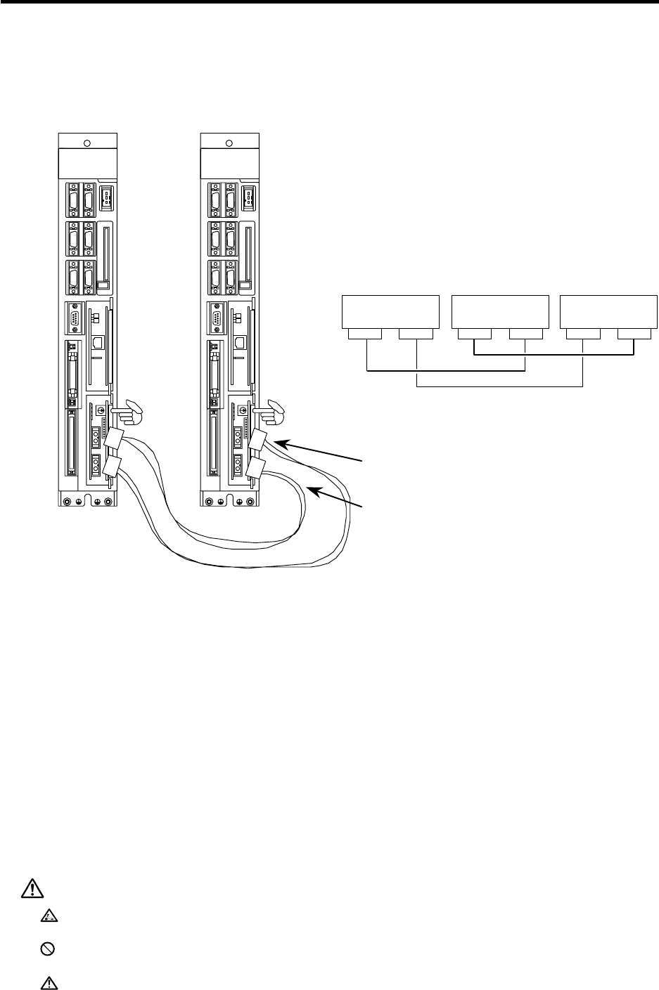
(2) Connecting the optical loop type MELSECNET/10
Connect a dedicated optical fiber cable to the optical connector on the MELSECNET/10 unit
(FCU6-EX879).
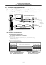
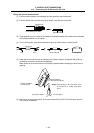
(Note 1) An indoor standard cable AS-2P-5M-A, etc., is
recommended for the optical fiber cable. Consult
with Mitsubishi Electric System Service.
(Note 2) The optical loop system's optical module follows
SI specifications. The total distance within one
network is 30km, and the distance between
stations is 500m.
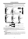
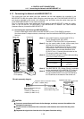
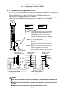
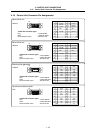
(Note 3) The optical loop system is a double loop
transmission path method. The following system
is used to connect the optical fiber cables.
MELSEC
NET/10
OUT T(F-SD)
→
Main loop transmission
(F) SD (OUT T(F-SD))
OUT R(R-RD) ← Sub-loop transmission
(R) RD (OUT R(R-RD))
IN T(R-SD) → Sub-loop transmission
(R) SD (IN T(R-SD))
IN R(F-RD) ← Main loop transmission
(F) RD (IN R(F-RD))
Control unit
LED1
Control unit
LED1
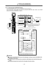
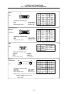
IN : Connect to OUT on previous station
OUT : Connect to IN on next station
(Connection example)
Station No.1
OUT IN OUT IN
INOUT
Station No.2
Station No.3
CAUTION
Incorrect connections could cause device damage, so always connect the cables to the
designated connectors.
Do not connect or disconnect the connection cable between each unit while the power
is ON.
Separate the signal wire from the drive line/power line when wiring.