


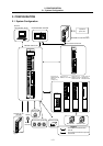
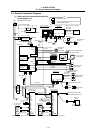
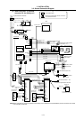
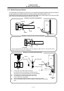
3. INSTALLATION
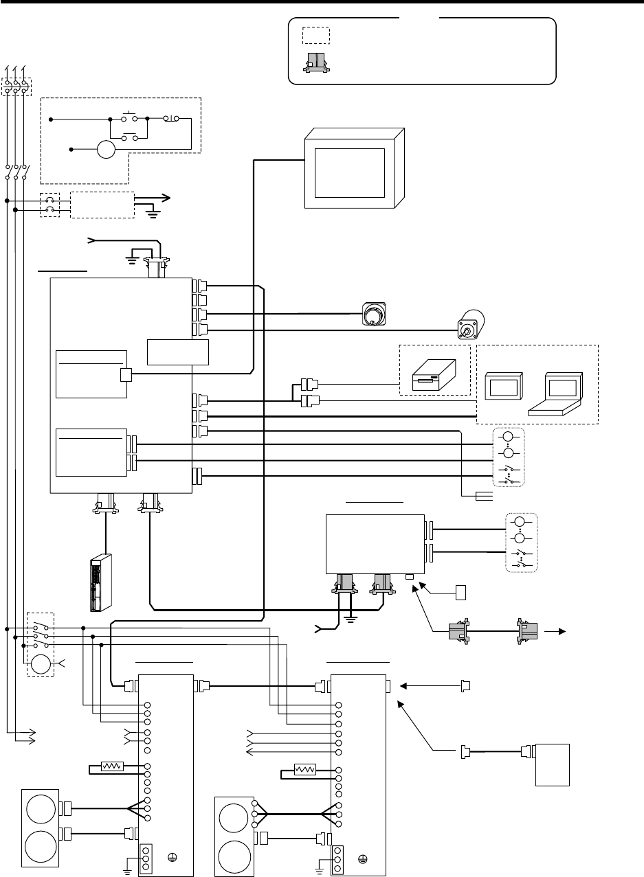
3.2 General Connection Diagram
I - 9
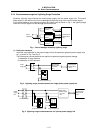
CN1A CN1B
L2
L3
C
L1
L21
MC1
N
D
U
V
W
FG
FG
FG
CN2
L1
P
CN1A CN1B
L2
L3
C
L1
L21
MC1
N
D
U
V
W
FG
FG
FG
CN2
P
L1
IM
Detector
SM
Spindle motor
with detecto
r
A
C servomoto
r
with detecto
r
Spindle drive unit
MDS-B-SPJ2-□□
Servo drive unit
MDS-B-SVJ2-□□
MC link A Terminator
A
-TM
For standard specifications final axis
For absolute position
specifications final axis
CN1A1
R000 cable
Battery unit
BT-□
: User-prepared parts
: Connectors enclosed with remote I/O unit and
communication terminal
R S T
No-fuse breaker (NFB)
3-phase 200VAC to 230VAC
Stabilized
power supply
DC24V
FG
DC24V
R220 cable
C6
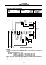
IC memory card
Expansion card 2
(Ethernet)
Expansion card 1
(When DIO card
is selected.)
R211 cable
SERVO2
HANDLE
ENC
SIO
SERVO1
TERMINAL
SKIP
DIO
RIO-M
RIO-M/S
DCIN
RS-232C cable
RS-422 cable
F340 cable
F351 cable
F351 cable
F350 cable
Machine control
relay/contact
Machine control
relay/contact
R
R
R
R
MC link B Terminator R-TM
or
To next remote
I/O unit
R211
cable
DCIN RIO1 RIO2
DC24V
FG
R220 cable
Remote I/O unit
DX1□□
R300 cable
/R301 cable
R300 cable
/R301 cable
R000
cable
RS-232C device
Sensor contact
Max. 4 points
Manual pulse generator
FCUA-HD60
Synchronous feed encoder
OSE1024-3-15-□□
F320 cable/F321 cable
/F322 cable
R050 cable/R051 cable
R054 cable/R055 cable
Insert when required
OFF
ON
MC
MC
L11
L21
L11
L21
L11
L21
MC1
Regenerative resisto
r
FCUA-□□
Regenerative resistor
FCUA-□□
MC1
MC1
MC1
GOT
Key
MC
R211 cable
DI
DO
CNV2 cable
/CNV12 cable
NFB
To next unit
R000 cable
CNV2 cable
/CNV12 cable
Ethernet cable
FG
Control unit
F310 cable
/F311 cable
/F312 cable
GOT
Personal computer
(GX-Developer)
RS-232C cable
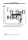
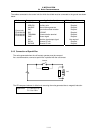
(2) When using GOT or personal
computer for the display unit
Detector
(Note) When using GOT or personal computer for the display unit, an Ethernet card (FCU6-EX875) must be mounted in the control
unit's extension slot (EXT2).