


6. CONNECTION OF REMOTE I/O UNIT
6.6 Outline of Digital Signal Output Circuit
I - 61
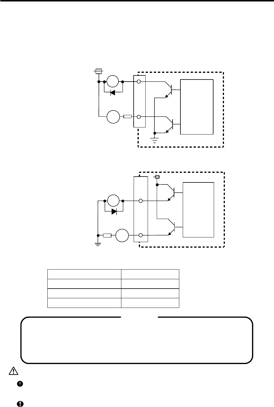
6.6 Outline of Digital Signal Output Circuit
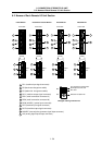
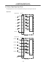
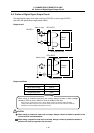
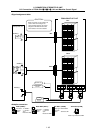
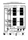
The digital signal output circuit uses a sink type (DX10) or source type (DX11).
Use within the specification ranges shown below.
Output circuit
R
(Machine side)
Control
circuit
24VDC(+)
Sink type (DX1
0)
RA
PL
DO-L/DO-R
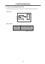
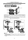
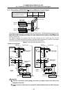
R
Source (DX1
1)
RA
PL
24VDC(+)
DO-L/DO-R
(Machine side)
Control
circuit
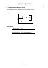
Output conditions
Insulation method Non-insulation
Rated load voltage 24VDC
Max. output current 60mA
Output delay time 40µs
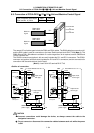
When using an inductive load such as a relay, always connect a diode (voltage
resistance 100V or more, 100mA or more) in parallel to the load.
When using a capacity load such as a lamp, always connect a protective resistor (R=150
Ω
)
serially to the load to suppress rush currents. (Make sure that the current is less than the above
tolerable current including the instantaneous current.)
<CAUTION
>
CAUTION
When using an inductive load such as relays, always connect a diode in parallel to the
load as a noise countermeasure.
When using a capacitive load such as a lamp, always connect a protective resistor in
series to the load to suppress rush currents.