


3. INSTALLATION
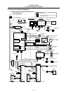
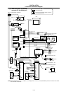
3.2 General Connection Diagram
I - 10
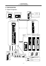
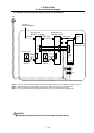
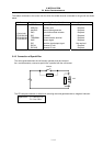
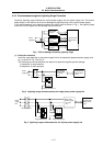
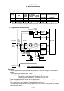
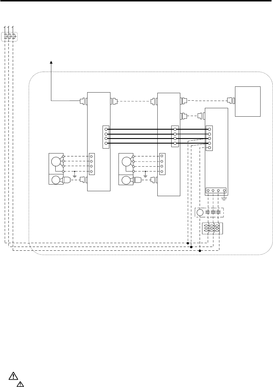
(3) Example of Connection when Using V1/V2/SP for Drive Section
Connect to
control unit SERVO1
AC servomoto
r
Motor end
detector
Spindle motor
Battery
unit
R000 cable
Motor end
detector
R000 cable
R000 cable
Power
supply
unit
MDS-A-BT-4(4-axis)
MDS-A-BT-2(2-axis)
CN4
CN4
CN1A CN1B
U
V
W
E
L+
L-
L11
L21
(Note 2)
SM
IM
ENC
ENC
L+
L-
L11
L21
MC1
Spindle drive unit
MDS-B/C1-SP-
Servo drive unit
MDS-B/C1-V1/V2-
CN2CN2
L1 L2 L3 E
MC
B-AL
R S T
CN1A CN1B
U
V
W
E
(Note 1) The drive section connection will differ according to the configuration of the servo amplifier and motor being used.
(Note 2) The R000 cable has the same specifications (connector types and connections) as the SH21 cable.
(Note 3) When connecting the spindle amplifier, set the axis No. to the value after the last servo axis.
(Note 4) The axis connected to the power supply unit is the last axis, or the axis connected to the battery unit.
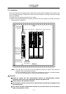
CAUTION
Separate the signal wire from the drive line/power line when wiring.