


4. CONNECTION OF SERVO AMPLIFIER AND SERVO MOTOR
4 - 2
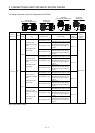
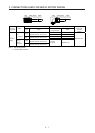
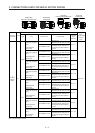
4.1 Connection instructions
CAUTION
To avoid a malfunction, connect the wires to the correct phase terminals (U, V,
and W) of the servo amplifier (converter unit) and servo motor.
Do not connect AC power supply directly to the servo motor. Otherwise, it may
cause a malfunction.
Do not use the 24 V DC interface power supply for the electromagnetic brake.
Always use the power supply designed exclusively for the electromagnetic brake.
Otherwise, it may cause a malfunction.
POINT
Refer to chapter 5 for the selection of the encoder cable.
Refer to the chapter of the servo motor series for the selection of a surge
absorber for the electromagnetic brake.
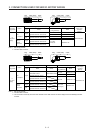
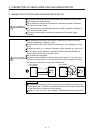
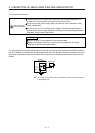
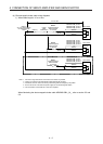
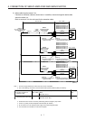
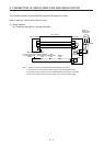
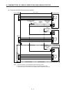
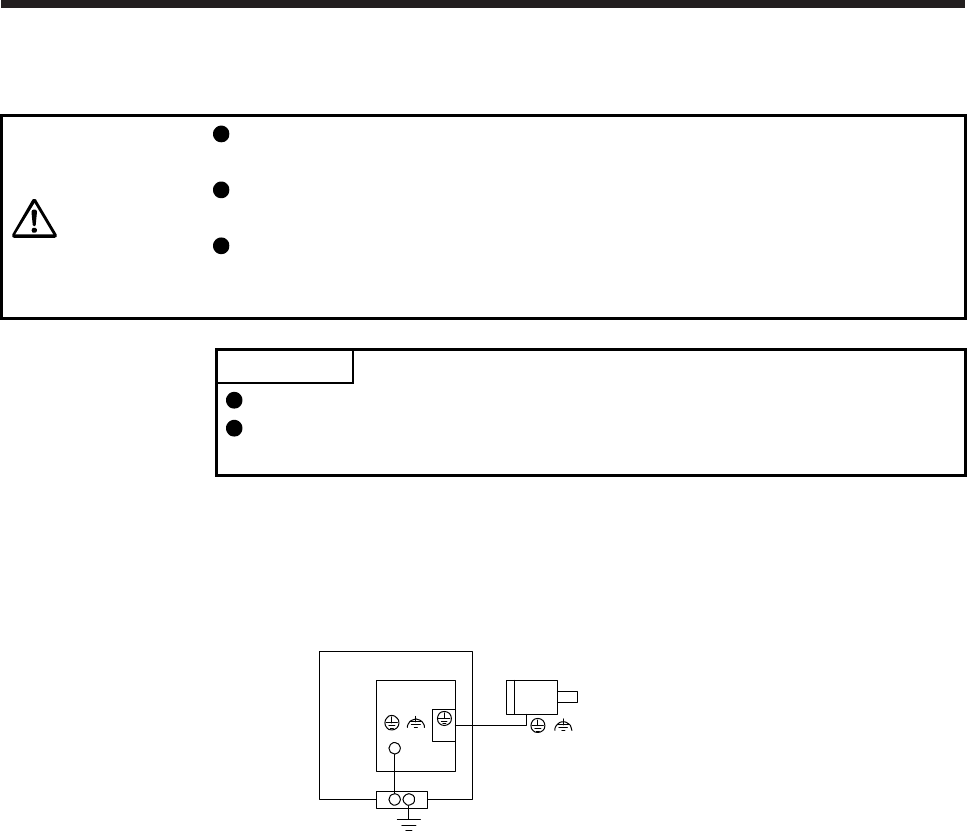
For grounding, connect the grounding lead wire from the servo motor to the protective earth (PE) terminal of
the servo amplifier (converter unit), and then connect the wire from the servo amplifier (converter unit) to the
ground via the protective earth of the cabinet. Do not connect the wire directly to the protective earth of the
cabinet.
Servo motor
Servo amplifier
(converter unit)
Cabinet
PE
terminal
(Note)
(
()
)
(E)
Note. The number of PE terminals of the servo amplifier (converter unit) differs depending
on the amplifier types.