


BIOS Intel® Server Board SE7501WV2 TPS
Revision 1.0
Intel reference number C25653-001
118
6.40 Logging Format Conventions
The BIOS complies with Version 1.5 of the Intelligent Platform Management Interface
Specification. IPMI specifications 0.9, 1.0, and 1.5 define the required use of all but two bytes in
each event log entry, Event Data 2 and Event Data 3. An event generator can specify that these
bytes contain OEM-specified values. The system BIOS uses these two bytes to record
additional information about the error.
The format of the OEM data bytes (Event Data 2 and Event Data 3) for memory errors, PCI bus
errors and FRB-2 errors has been standardized and is described here. Although only one format
is defined in this version, this specification allows for multiple formats. This format is supported
by all platforms that are compliant with IPMI Version 1.0 (or later).
Bits 3:1 of the generator ID field define the format revision. The system software ID is a 7-bit
quantity. For events discussed in this document, the system software IDs are within the range
0x18 – 0x1F. System software ID of 0x18 indicates that OEM data byte 2 and 3 are encoded
using data format scheme revision 0. The current document defines revision 0 of the format.
System software IDs in the range of 0x10 through 0x1f are reserved for the SMI handler. The
IPMI specification reserves two distinct ranges for the BIOS and SMI handler. Since the
distinction between the two is not significant, the same generator ID values are used for the
BIOS and the SMI handler. Technically, the FRB-2 event is not logged by the SMI handler, but it
will use the same generator ID range as memory errors. This makes it easier for the BIOS and
the event log parser code.
The BIOS logs events using the discrete event trigger class. For this class, the format of the
event data bytes is defined in Table 17.5 of the Intelligent Management Platform Interface
Specification.
The system BIOS sensors are logical entities that generate events. The BIOS ensures that each
combination of sensor type (e.g., memory) and event type (e.g., sensor-specific) has a unique
sensor number.
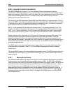
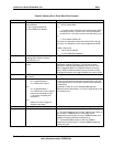
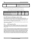
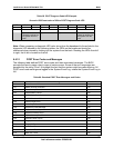
6.40.1 Memory Error Events
The following table defines the data byte formats for memory-related errors logged by the BIOS.
Memory errors, both correctable and uncorrectable cause an SMI. The BIOS then reads the
current memory error state from the North Bridge to generate IPMI sensor events. The BIOS will
count the number of correctable memory errors that occur on each DIMM over time. If more
than 10 errors occur on a DIMM within an hour, an Event Logging Disabled event will be
generated and logging of correctable errors will be stopped until the next reset or power-on. If
the BIOS detects an uncorrectable error, it will generate an Uncorrectable ECC event against
the memory sensor and set the failed offset in the associated DIMM sensor (if a failing DIMM
can be determined).