


Intel® Server Board SE7501WV2 TPS SE7501WV2 Connectors
Revision 1.0
Intel reference number C25653-001
143
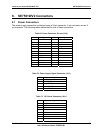
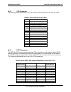
8.4 System Management Headers
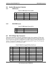
8.4.1 ICMB Header
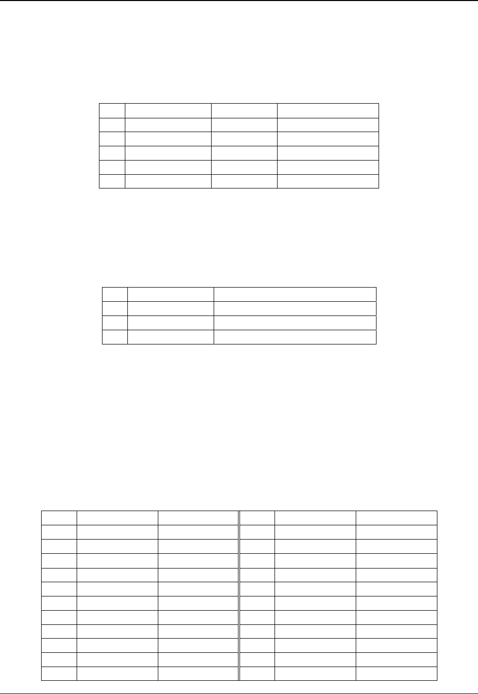
Table 74. ICMB Header Pin-out (J9B2)
Pin Signal Name Type Description
1 5 V standby Power +5 V Standby
2 Transmit Signal UART signals
3 Transmit Enable Signal UART signals
4 Receive Signal UART signals
5 Ground GND Ground
8.4.2 OEM IPMB Header
Table 75. IPMB Header Pin-out (J9C1)
Pin Signal Name Description
1 Local I2C SDA BMC HI 5 V Standby Clock Line
2 GND Ground
3 Local I2C SCL BMC HI 5 V Standby Data Line
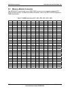
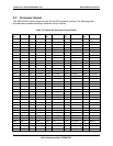
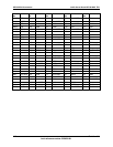
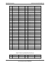
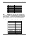
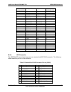
8.5 PCI I/O Riser Slot Connector
There are two peer 64-bit, PCI buses implemented through the two separate I/O Riser slots
(PCI-X B, PCI-X C). The first PCI segment, P64-B, supports full length, full height PCI cards.
The PCI cards must meet the PCI specification for height, inclusive of cable connections and
memory. The second PCI segment, P64-C, supports low-profile PCI cards. The I/O riser slot
pin-outs are detailed in the following two tables.
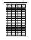
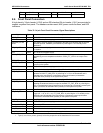
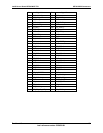
Table 76. P64-B Full Length PCI Riser Slot Pin-out
Pin Side B Side A Pin Side B Side A
1 -12 V TRST# 49 M66EN AD[09]
2 IRQ5 +12 V 50
Connector Key Connector Key
3 Ground TMS 51
Connector Key Connector Key
4 IRQ4 TDI 52 AD[08] C/BE[0]#
5 +5 V +5 V 53 AD[07] +3.3 V
6 +5 V IRQ0 54 +3.3 V AD[06]
7 IRQ3 IRQ1 55 AD[05] AD[04]
8 IRQ3 +5 V 56 AD[03] Ground
9 PRSNT1# REQ3# 57 Ground AD[02]
10 GNT2# +5 V 58 AD[01] AD[00]
11 PRSNT2# GNT3# 59 +5 V +5 V