


BIOS Intel® Server Board SE7501WV2 TPS
Revision 1.0
Intel reference number C25653-001
134
The following code fragment shows the header and format for a user binary:
db 55h, 0AAh, 20h ; 8KB USER Area
MyCode PROC FAR ; MUST be a FAR procedure
db CBh ; Far return instruction
db 04h ; Bit map to define call points, a
; 1 in any bit specifies
; that the BIOS is called at that
; scan point in POST
db CBh ; First transfer address used to
; point to user binary extension structure
dw ? ; Word Pointer to extension structure
dw 0 ; Reserved
JMP ErrRet ; This is a list of 7 transfer
; addresses, one for each
JMP ErrRet ; bit in the bitmap.
; 5 Bytes must be used for each
JMP Start ; JMP to maintain proper offset for
; each entry. Unused entry JMP’s
; should be filled with 5 byte
; filler or JMP to a RETF
JMP ErrRet ;
JMP ErrRet
JMP ErrRet
JMP ErrRet
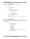
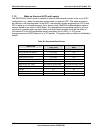
6.48.1 Scan Point Definitions
Table 66 defines the bitmap for each scan point, indicating when the scan point occurs and
which resources are available (RAM, stack, binary data area, video, keyboard).
Table 66. User Binary Area Scan Point Definitions
Scan Point Mask RAM/Stack/BDA Video/Keyboard
Near the pointer to the user binary extension structure. The mask bit
is 0 if this structure is not present. Instead of a jump instruction, the
scan address (offset 5) contains a 0CB followed by a near pointer.
01h Not applicable Not applicable
Obsolete, no action taken. 02h Not applicable Not applicable
This scan occurs immediately after video initialization. 04h Yes Yes
This scan occurs immediately before video initialization 08h Yes No
This scan occurs on POST error. On entry, BX contains the number of
the POST error
10h Yes Yes
This final scan occurs immediately prior to the INT 19 for normal boot
and allows one to completely circumvent the normal INT 19 boot if
desired.
20h Yes Yes
This scan occurs immediately before the normal option ROM scan. 40h Yes Yes
This scan occurs immediately following the option ROM area scan. 80h Yes Yes