


Intel® Server Board SE7501WV2 TPS SE7501WV2 Connectors
Revision 1.0
Intel reference number C25653-001
153
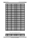
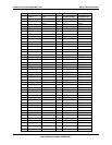
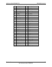
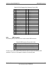
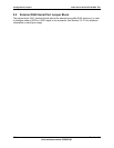
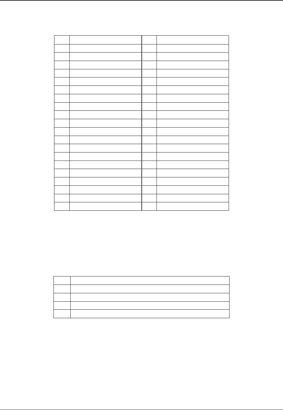
Table 85. ATA-100 Legacy 40-pin Connector Pinout (J1G2)
Pin Signal Name Pin Signal Name
1 RESET_L 2 GND
3 DD7 4 IDE_DD8
5 DD6 6 IDE_DD9
7 DD5 8 IDE_DD10
9 DD4 10 IDE_DD11
11 DD3 12 IDE_DD12
13 DD2 14 IDE_DD13
15 DD1 16 IDE_DD14
17 DD0 18 IDE_DD15
19 GND 20 KEY
21 IDE_DMAREQ 22 GND
23 IDE_IOW_L 24 GND
25 IDE_IOR_L 26 GND
27 IDE_IORDY 28 GND
29 IDE_DMAACK_L 30 GND
31 IRQ_IDE 32 Test Point
33 IDE_A1 34 Test Point
35 IDE_A0 36 IDE_A2
37 IDE_DCS0_L 38 IDE_DCS1_L
39 IDE_HD_ACT_L 40 GND
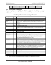
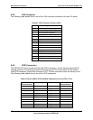
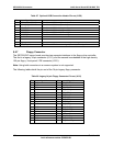
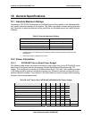
8.6.6 USB Connector
The following table provides the pin-out for both external USB connectors.
Table 86. USB Connectors Pin-out (J4A1, J9A1)
Pin Signal Name
1 Fused VCC (+5V /w over current monitor of both port 0 and 1)
2 DATAL0 (Differential data line paired with DATAH0)
3 DATAH0 (Differential data line paired with DATAL0)
4 GND
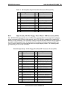
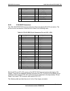
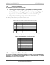
A header on the server board (J1D3) provides an option to support two additional USB
connectors. The pin-out of the header is detailed in the following table.