


Intel® Server Board SE7501WV2 TPS BIOS
Revision 1.0
Intel reference number C25653-001
121
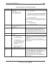
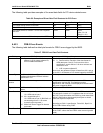
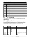
The following table provides examples of the event data fields for PCI device-related errors.
Table 56. Examples of Event Data Field Contents for PCI Errors
Error Type Event Data 1 Event Data 2 Event Data 3
PCI PERR, failing device is not known 04 0xFF 0xFF
PCI SERR, failing device is not known 05 0xFF 0xFF
PCI PERR, device 3, function 1 on PCI bus 5 reported
the error
0xA4 0x05 0x19
(Bits 7:3 = 03
Bits 2:0 = 01)
An unknown device on PCI bus 0 reported the SERR 0x85 0x00 0xFF
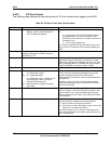
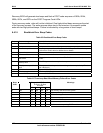
6.40.3 FRB-2 Error Events
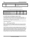
The following table defines the data byte formats for FRB-2 errors logged by the BIOS.
Table 57. FRB-2 Event Data Field Contents
Field IPMI Definition BIOS Specific Implementation
Generator ID 7:1 System software ID or IPMB slave
address. 1=ID is system software ID;
0=ID is IPMB slave address
7:4 0x3 for system BIOS
3:1 0 Format revision, Revision of the data format for
OEM data bytes 2 and 3, For this revision of the
specification, set this field to 0. All other revisions are
reserved for now.
0 1=ID is system software ID
As a result, the generator ID byte will start from 0x31 and go
up to 0x3f, in increments of 2 for events logged by the BIOS.
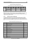
Sensor Type See Table 34.3, Sensor Type Codes, in the
Intelligent Management Platform Interface
Specification v1.5.
0x7 for processor related errors
Sensor
number
Number of sensor that generated this event Unique value for each type of event because IPMI
specification requires that. This field has no other
significance, and it should not be displayed to the end user if
the event is logged by BIOS.
Type code 0x6F if event offsets are specific to the
sensor
0x6F
Event Data 1 7:6 00 = unspecified byte 2
10 = OEM code in byte 2
5:4 00 = unspecified byte 3
10 = OEM code in byte 3. (BIOS will not
use encodings 01and 11 for errors
covered by this document.)
3:0 Offset from Event Trigger for discrete
event state.
If Event data 2 and event data 3 contain OEM codes, bits
7:6 and bits 5:4 contain 10. For platforms that do not include
the POST code information with FRB-2 log, both these fields
will be 0. BIOS either should specify both bytes or should
mark both bytes as unspecified.
According to IPMI 1.0 specification, Table 30.3, Byte 3:0 is
03 for FRB-2 failure during POST.
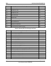
Event Data 2 7:0 OEM code 2 or unspecified For format rev 0, if this byte is specified, it contains bits 7:0
of the POST code at the time FRB-2 reset occurred (port 80
code)