Configuration and Initialization Intel® Server Board SE7501WV2 TPS
Revision 1.0
Intel reference number C25653-001
52
bus). The I/O APICs monitor each interrupt on each PCI device including PCI. When an
interrupt occurs, a message corresponding to the interrupt is sent across the FSB processors.
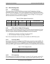
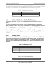
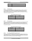
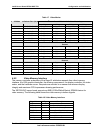
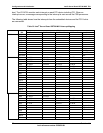
The following table shows how the interrupts from the embedded devices and the PCI-X slots
are connected.
Table 20. Intel
®
Server Board SE7501WV2 Interrupt Mapping
Device
IRQ
PCI Riser Connector PCI Riser Slot 1 PCI Riser Slot 2 PCI Riser Slot 3 Other
IRQA P64H2
IRQB Video
IRQC Promise ATA
IRQD
IRQE
IRQF
IRQG
IRQH
IRQ14 Pri IDE
IRQ15 Sec IDE
ICH3
SER IRQ SIO
IRQ0 LP INTA LP INTA LP INTD LP INTC
IRQ1* LP INTC LP INTC SCSI INTB
IRQ2* LP INTD LP INTD SCSI INTA
IRQ3 LP INTB LP INTB LP INTA LP INTD
IRQ4 LP TDO LP INTB LP INTA
IRQ5 LP TCK LP INTC LP INTB
IRQ6
IRQ7
IRQ8
IRQ9
IRQ10
IRQ11
IRQ12
IRQ13
IRQ14
P64H2 Ch A
IRQ15
IRQ1 FL INTC FL INTC
IRQ2 FL INTD FL INTD
IRQ3 FL INTB FL INTB FL INTA FL INTD
IRQ4 FL TDO FL INTB FL INTA
IRQ5 FL TCK FL INTC FL INTB
IRQ6 Gigabit Ch A
IRQ7 Gigabit Ch B
IRQ8
IRQ9
IRQ10
P64H2 Ch B
IRQ11


