


Server Management Intel® Server Board SE7501WV2 TPS
Revision 1.0
Intel reference number C25653-001
62
Near the end of POST, before the option ROMs are initialized, the BIOS disables the FRB-2
timer in the BMC. If the system contains more than 1 GB of memory and the user chooses to
test every DWORD of memory, the watchdog timer is disabled before the extended memory test
starts, because the memory test can take more than 6 minutes under this configuration. If the
system hangs during POST, the BIOS does not disable the timer in the BMC, which generates
an asynchronous system reset (ASR).
5.1.1.3 FRB-3
The first timer (FRB-3) starts counting down whenever the system comes out of hard reset,
which is usually about 5 seconds. If the BSP successfully resets and starts executing, the BIOS
disables the FRB-3 timer in the BMC by de-asserting the FRB3_TIMER_HLT* signal (GPIO)
and the system continues with the POST. If the timer expires because of the BSP’s failure to
fetch or execute BIOS code, the BMC resets the system and disables the failed processor. The
system continues to change the bootstrap processor until the BIOS POST gets past disabling
the FRB-3 timer in the BMC. The BMC sounds beep codes on the speaker, if it fails to find a
good processor. The process of cycling through all the processors is repeated upon system
reset or power cycle.
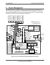
5.2 System Reset Control
Reset circuitry on the SE7501WV2 server board looks at resets from the front panel, ICH3-S,
ITP, and the processor subsystem to determine proper reset sequencing for all types of resets.
The reset logic is designed to accommodate several methods to reset the system, which can be
divided into the following categories:
• Power-up reset
• Hard reset
• Soft (programmed) reset
The following subsections describe each type of reset.
5.2.1 Power-up Reset
When the system is disconnected from AC power, all logic on the server board is powered off.
When a valid input (AC) voltage level is provided to the power supply, 5-volt standby power will
be applied to the server board. The baseboard has a 5-volt to 3.3-volt regulator to produce
3.3-volt standby voltage. A power monitor circuit on 3.3-volt standby will assert BMCRST_L,
causing the BMC to reset. The BMC is powered by 3.3-volt standby and monitors and controls
key events in the system related to reset and power control.
After the system is turned on, the power supply will assert the RST_PWRGD_PS signal after all
voltage levels in the system have reached valid levels. The BMC receives RST_PWRGD_PS and
after 500 ms asserts RST_P6_PWR_GOOD, which indicates to the processors and ICH3-S that
the power is stable. Upon RST_P6_PWR_GOOD assertion, the ICH3-S will toggle PCI reset.
5.2.2 Hard Reset
A hard reset can be initiated by resetting the system through the front panel switch. During the
reset, the Sahalee BMC de-asserts RST_P6_PWR_GOOD. After 500 ms, it is reasserted, and
the power-up reset sequence is completed.
The Sahalee BMC is not reset by a hard reset; it is only reset when AC power is applied to the
system.