


SE7501WV2 Connectors Intel® Server Board SE7501WV2 TPS
Revision 1.0
Intel reference number C25653-001
150
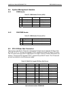
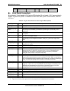
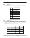
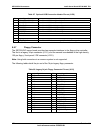
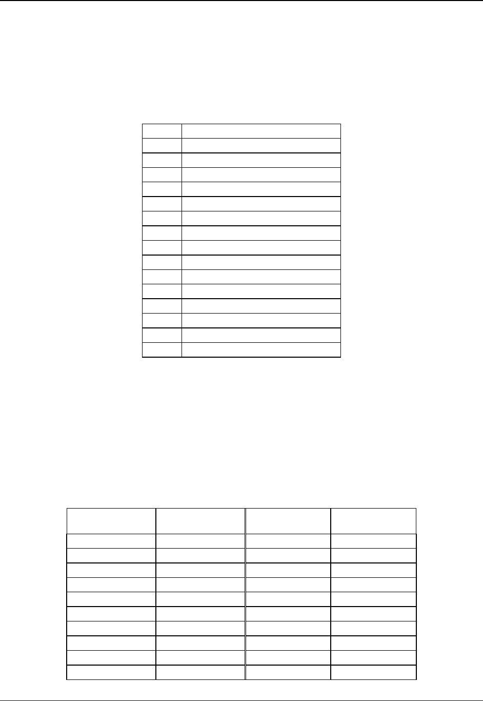
8.6.2 VGA Connector
The following table details the pin-out of the VGA connector (located on the rear I/O panel).
Table 81. VGA Connector Pin-out (J8A1)
Pin Signal Name
1 Red (analog color signal R)
2 Green (analog color signal G)
3 Blue (analog color signal B)
4 No connection
5 GND
6 GND
7 GND
8 GND
9 No connection
10 GND
11 No connection
12 DDCDAT
13 HSYNC (horizontal sync)
14 VSYNC (vertical sync)
15 DDCCLK
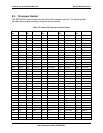
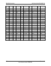
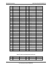
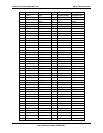
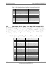
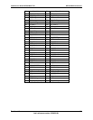
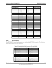
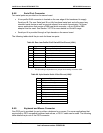
8.6.3 SCSI Connectors
The SE7501WV2 server board provides two SCSI connectors, one for the high density SCSI
external (channel A) connector (located on the rear panel I/O), and the other for the internal
wide SCSI connector (channel B) connector J7B1. The two connectors have the same pin-out.
The following table details the pin-out of the SCSI connectors.
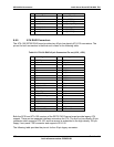
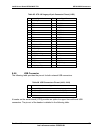
Table 82. 68-pin VHDCI SCSI and Wide Connectors Pin-out (J7B1, J7A1)
Connector
Contact Number
Signal Name Signal Name Connector
Contact Number
1 +DB(12) -DB(12) 35
2 +DB(13) -DB(13) 36
3 +DB(14) -DB(14) 37
4 +DB(15) -DB(15) 38
5 +DB(P1) -DB(P1) 39
6 +DB(0) -DB(0) 40
7 +DB(1) -DB(1) 41
8 +DB(2) -DB(2) 42
9 +DB(3) -DB(3) 43
10 +DB(4) -DB(4) 44