


Functional Architecture Intel® Server Board SE7501WV2 TPS
Revision 1.0
Intel reference number C25653-001
34
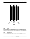
3.3.2.1 Serial Port A
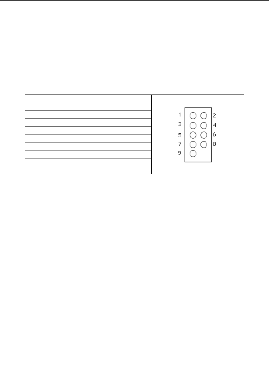
Serial A is an optional port, accessed through a 9-pin internal header (J9A2). A standard DH-10
to DB9 cable can be used to direct Serial A out the back of a given chassis. The Serial A
interface follows the standard RS232 pin-out. The baseboard has a Serial Port A silkscreen
label next to the connector as well as a location designator of J9A2. The Serial A connector is
located next to the P64-C low-profile PCI card slot. A standard DH-10 to DB9 cable is available
from Intel Corporation in the SE7501WV2 Serial Port Accessory Kit.
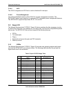
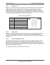
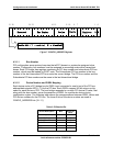
Table 7. Serial A Header Pin-out
Pin Signal Name Serial Port A Header Pin-out
1 DCD
2 DSR
3 RX
4 RTS
5 TX
6 CTS
7 DTR
8 RI
9 GND
3.3.2.2 Serial Port B
Serial B is an external low profile 8-pin RJ45 connector that is located on the back of the board.
For those server applications that require an external modem, an RJ45-to-DB9 adapter is
necessary. A standard DH-10 to DB9 cable is available from Intel in the SE7501WV2 Serial Port
Accessory Kit.
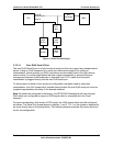
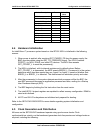
3.3.2.3 Serial Port Multiplexer Logic
The SE7501WV2 server board has a multiplexer to connect the rear RJ45 connector to either
Serial Port A or Serial Port B in both the Intel® Server Chassis SR1300 and SR2300. This
facilitates the routing of Serial Port A to the rear RJ45 connector if Serial Port B is used for SOL
(Serial Over LAN) in both the SR1300 and SR2300 server chassis. This serial port selection can
be done through the BIOS setup option.
The following figure shows the serial port mux functionality.