


Intel® Server Board SE7501WV2 TPS Configuration and Initialization
Revision 1.0
Intel reference number C25653-001
41
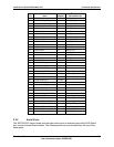
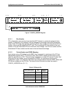
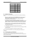
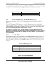
Device Description Bus Device ID
(Hex)
RMC Connector 1 0A
P64H2 P2P Bridge A 2 1F
P64H2 P2P Bridge B 2 1D
Dual Gigabit NIC 3 07
PCI Slot 1B 3 08
PCI Slot 2B 3 09
PCI Slot 3B 3 0A
SCSI 4 07
PCI Slot 1C 4 08
PCI Slot 2C 4 09
PCI Slot 3C 4 0A
4.4 Hardware Initialization
An Intel® Xeon™ processor system based on Intel E7501 MCH is initialized in the following
manner.
1. When power is applied, after receiving RST_PWRGD_PS from the power supply, the
BMC provides resets using the RST_P6_PWRGOOD signal. The ICH3-S asserts
PCIRST_L to MCH, P64H2, and other PCI devices. The MCH then asserts
RST_CPURST_L to reset the processor(s).
2. The MCH is initialized, with its internal registers set to default values. Before
RST_CPURST_L is deasserted, the MCH asserts BREQ0_L. Processor(s) in the system
determine which host bus agents they are, Agent 0 or Agent 3, based on whether their
BREQ0_L or BREQ1_L is asserted. This determines bus arbitration priority and order.
3. After the processor(s) in the system determines which processor will be the BSP, the
non-BSP processor becomes an application processor and idles, waiting for a Startup
Inter Processor Interrupt (SIPI).
4. The BSP begins by fetching the first instruction from the reset vector.
5. The Intel® E7501 chipset registers are updated to reflect memory configuration. DIMM is
sized and initialized.
6. All PCI and ISA I/O subsystems are initialized and prepared for booting.
Refer to the SE7501WV2 BIOS EPS for more details regarding system initialization and
configuration.
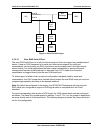
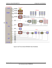
4.5 Clock Generation and Distribution
All buses on the SE7501WV2 baseboard operate using synchronous clocks. Clock
synthesizer/driver circuitry on the baseboard generates clock frequencies and voltage levels as
required, including the following: