


Intel® Server Board SE7501WV2 TPS SE7501WV2 Connectors
Revision 1.0
Intel reference number C25653-001
155
8.6.8 Serial Port Connector
Two serial ports are provided on the server board.
• A low-profile RJ45 connector is located on the rear edge of the baseboard to supply
Serial port B. The rear Serial port B is a fully functional serial port and will support any
standard serial device as well as provide support for a serial concentrator. For those
server applications that require a DB9 type serial connector, a 8-pin RJ45-to-DB9
adapter must be used. See Section 3.3.2.2 for more details on Serial B usage.
• Serial port A is provided through a 9-pin header on the server board.
The following tables detail the pin-outs for these two ports.
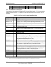
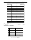
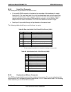
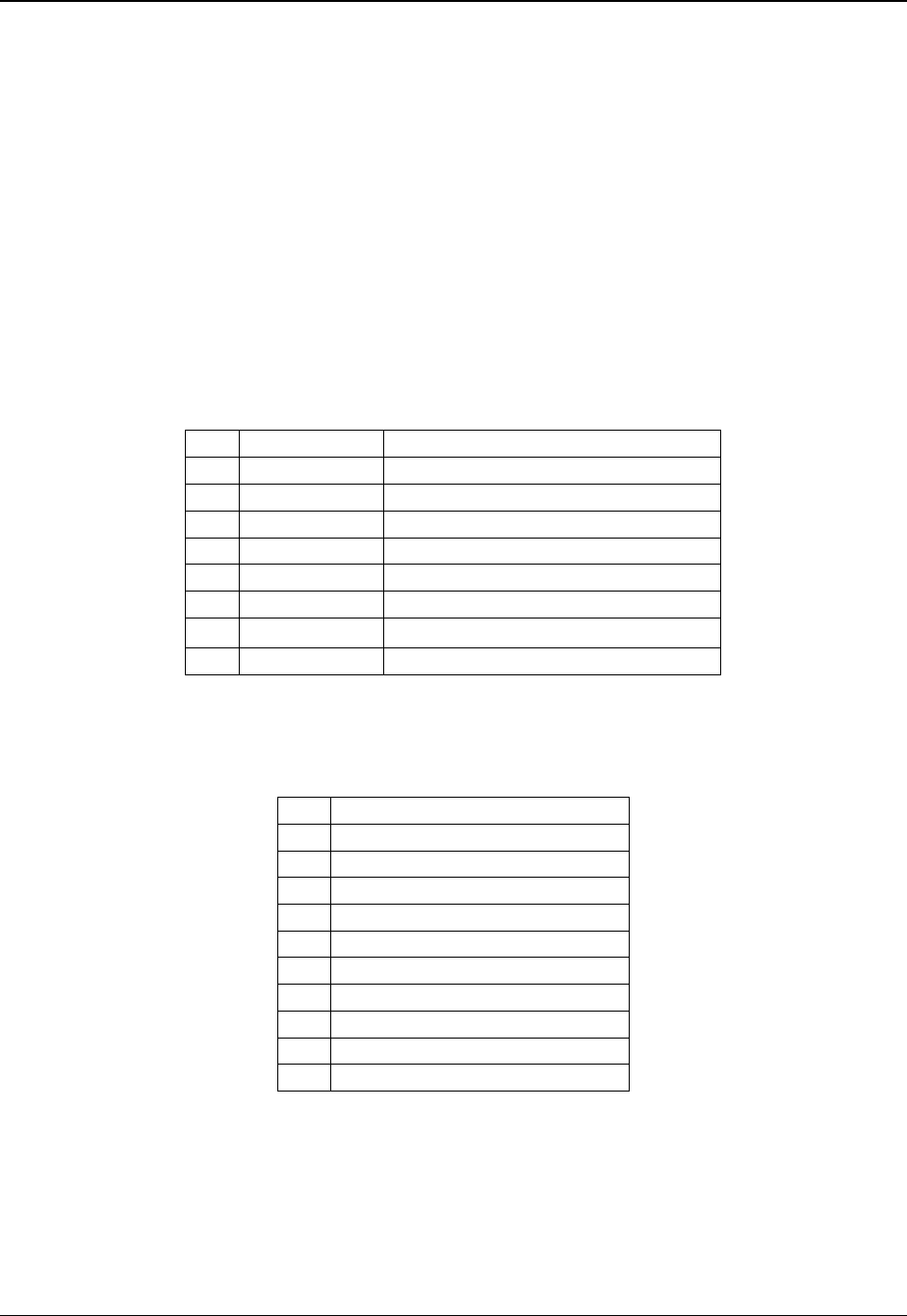
Table 89. Rear Low-Profile RJ-45 Serial B Port Pin-out (J5A1)
Pin Signal Name Description
1 RTS Request To Send
2 DTR Data Terminal Ready
3 TD Transmit Data
4 SGND Signal Ground
5 RI Ring Indicate
6 RD Receive Data
7 DCD or DSR
Carrier Detect or Data Set Ready
1
8 CTS Clear to send
Note:
1. This pin setting is dependent on a jumper block setting at location J5A2.
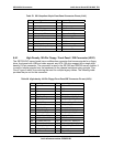
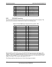
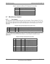
Table 90. 9-pin Header Serial A Port Pin-out (J9A2)
Pin Signal Name
1 DCD (carrier detect)
2 DSR (data set ready)
3 RD (receive data)
4 RTS (request to send)
5 TD (transmit data)
6 CTS (clear to send)
7 DTR (data terminal ready)
8 RI (ring indicate)
9 Ground
10 Missing pin
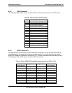
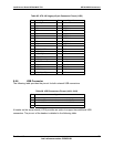
8.6.9 Keyboard and Mouse Connector
One PS/2 port is provided for use by either a keyboard or a mouse. For server applications that
require both a PS/2 compatible keyboard and mouse, a PS/2 Y-cable can be used. The following
table details the pin-out of the PS/2 connector.