


Functional Architecture Intel® Server Board SE7501WV2 TPS
Revision 1.0
Intel reference number C25653-001
36
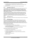
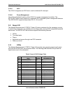
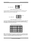
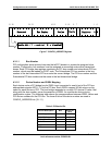
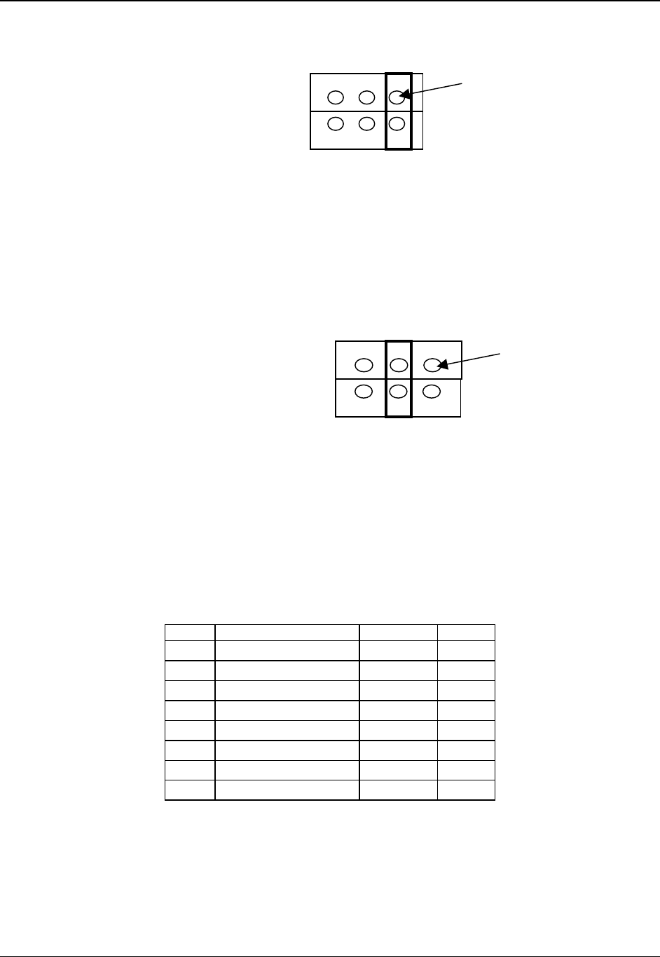
Figure 5. J5A2 Jumper Block for DCD Signal
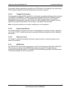
For serial concentrators that require a DSR signal (Default), the J5A2 jumper block must be
configured as follows: The Serial Port jumper in position 3 and 4. Pin 1 on the jumper is
denoted by an arrow directly next to the jumper block.
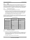
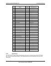
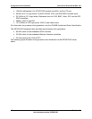
Figure 6. J5A2 Jumper Block for DSR Signal
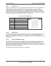
For those server applications that require a DB9 serial connector, an 8-pin RJ45-to-DB9 adapter
must be used. The following table provides the pin-out required for the adapter to provide
RS232 support. A standard DH-10 to DB 9 cable and 8-pin RJ45 to DB9 DCD & DSR adapters
are available from Intel in the Serial Accessory Kit.
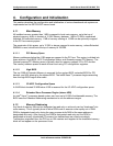
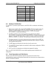
Table 8. Rear Serial Port B Adapter Pinout
RJ45 Signal Abbr. DB9
1 Request to Send RTS 7
2 Data Terminal Ready DTR 4
3 Transmitted Data TD 3
4 Signal Ground SGND 5
5 Ring Indicator RI 9
6 Received Data RD 2
7 DCD or DSR DCD/DSR 1 or 6*
8 Clear To Send CTS 8
Note: The RJ45-to-DB9 adapter should match the configuration of the serial device used. One
of two pin-out configurations is used depending on whether the serial device requires a DSR or
DCD signal. The final adapter configuration should also match the desired pin-out of the RJ45
connector, as it can also be configured to support either DSR or DCD.
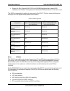
Pin 1
–
DCD to Pin #7
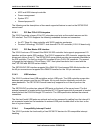
PIN 1
Pin 1 - DSR to Pin#7
PIN 1