Intel® Server Board SE7501WV2 TPS Configuration and Initialization
Revision 1.0
Intel reference number C25653-001
45
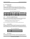
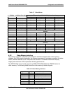
host bridge PCI interface (ICH) arbitration lines REQx* and GNTx* are special cases in that they
are internal to the host bridge. The following table defines the arbitration connections.
Table 12. P32-Arbitration Connections
Baseboard Signals Device
P32_REQ4*/P32_GNT1* Promise ATA-100 Controller ( ATA Version Only)
P32_REQ0*/P32_GNT0* ATA Rage XL video controller
4.6.3 P64-B and P64-C: 64-bit, 100-MHz PCI-X Subsystem
There are two peer 64-bit, 100-MHz PCI-X bus segments directed through the P64H2 I/O
Bridge.
The first PCI-X segment, P64-B, provides a single I/O Riser slot capable of supporting full
length, full height PCI cards. The PCI cards must meet the PCI specification for height, inclusive
of cable connections and memory. In addition to the riser connector, the P64-B segment also
has an Intel
®
82546EB dual channel Gigabit Ethernet controller.
The second PCI-X segment, P64-C, provides a second I/O riser slot. Because of physical
limitations of the baseboard, this riser slot is only capable of supporting low-profile PCI cards. In
addition to the riser connector, the P64-C segment also has an Adaptec* 7902 dual channel U-
320 SCSI controller.
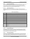
4.6.3.1 Device IDs (IDSEL)
Each device under the PCI hub bridge has its IDSEL signal connected to one bit of AD[31:16],
which acts as a chip select on the PCI bus segment in configuration cycles. This determines a
unique PCI device ID value for use in configuration cycles. The following tables show the bit to
which each IDSEL signal is attached for P64-B and P64-C devices, and corresponding device
description.
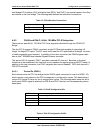
Table 13. P64-B Configuration IDs
IDSEL Value Device
23 On-board Gigabit Ethernet controller
24 First slot of the riser card
25 Second slot of the riser card ( for a 3-slot riser card)
26 Third slot of the riser card (for a 3-slot riser card)
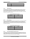
Table 14. P64-C Configuration IDsIDs
IDSEL Value Device


