


BIOS Intel® Server Board SE7501WV2 TPS
Revision 1.0
Intel reference number C25653-001
92
1. Power off the system, but leave the AC power connected so the 5 V standby is available.
2. Assure that the CMOS clear jumper is in the ‘not clear’ position.
3. Hold down the reset button for at least 4 seconds.
4. While reset button is still depressed, press the on / off button.
5. Simultaneously release both the on / off button and reset buttons.
Upon completion of these steps, the BMC asserts the clear CMOS signal to emulate the movement
of the clear CMOS jumper. The BIOS clears CMOS as if the user had moved the CMOS clear
jumper on the baseboard. CMOS is cleared only once per front panel button sequence. The BMC
releases the CMOS clear line during the next system reset. Removing the CMOS Clear jumper
from the baseboard can disable the Front Panel CMOS reset function. The jumper should be
retained in case the CMOS needs to be cleared using the baseboard header.
When the BIOS detects a reset CMOS request, CMOS defaults are loaded during the next
POST sequence. Note that non-volatile storage for embedded devices may or may not be
affected by the clear CMOS operation depending on the available hardware support. Refer to
the sections specific to this platform to determine which embedded device nonvolatile storage
areas are cleared during a clear CMOS operation.
6.19 BIOS Updates
There are two major changes to the current method of updating the BIOS code stored in Flash
memory on the SE7501WV2 platform. Currently, the BIOS updates are achieved via iFLASH
updates and by applying recovery procedures as mentioned in the Flash Update Utility section
below. In addition, the SE7501WV2 platform also supports On-line Update / Rolling BIOS
capability for the purpose of BIOS updates from the OS as described in the Rolling BIOS and
On-line updates section below.
6.19.1 Flash Update Utility
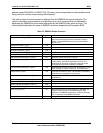
The Flash Memory Update utility (iFLASH) loads a fresh copy of the BIOS into flash ROM. The
loaded code and data include the following:
• On-board video BIOS, SCSI BIOS, and other option ROMs for the devices embedded on
the system board
• The Setup utility
• A user-definable flash area (user binary area)
When running iFLASH in interactive mode, the user may choose to update a particular Flash
area. Updating a Flash area reads a file, or a series of files, from a hard or floppy disk, and
loads it in the specified area of flash ROM. In interactive mode, iFLASH can display the header
information of the selected files.
Note: The iFLASH utility must be run without the presence of a 386 protected mode control
program, such as Windows* or EMM386*. iFLASH uses the processor’s flat addressing mode to
update the Flash component.