


Server Management Intel® Server Board SE7501WV2 TPS
Revision 1.0
Intel reference number C25653-001
54
5. Server Management
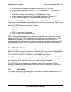
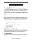
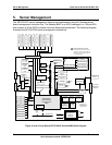
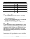
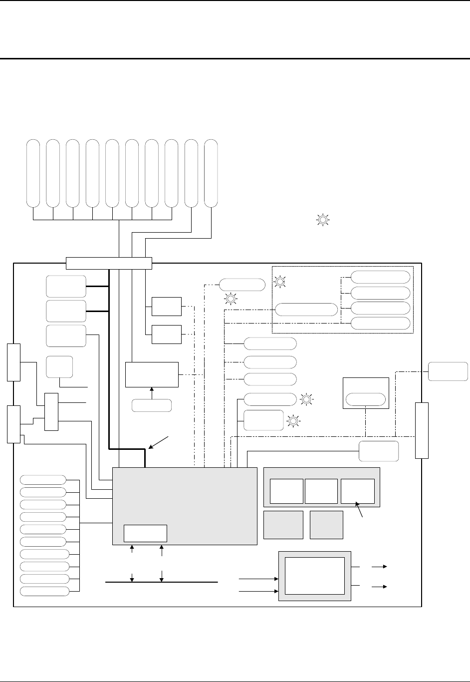
The SE7501WV2 server management features are implemented using the Sahalee server
board management controller chip. The Sahalee BMC is an ASIC packaged in a 156-pin BGA
that contains a 32-bit RISC processor core and associated peripherals. The following diagram
illustrates the SE7501WV2 server management architecture.
BASEBOARD
PROCESSOR SOCKETS
SMS
I/F
System Bus
5V
12V
3.3V
-12V
Power Button
Front Panel NMI Switch
IERR (2)
Thermal Trip (2)
- Chassis ID
- Baseboard ID
- Power State
NMI
Chip set NMIs
Chip set SMI
CPU Voltage (2)
INTELLIGENT PLATFORM
MANAGEMENT BUS (IPMB)
Reset Button
Chassis Intrusion
Power Connector
To Power
Distributio
n
Board
Private Management Busses
RAM
CODE
(updateable)
SMI
Platform
Management
Interrupt
Routing
Non-volatile, read-write storage
SENSOR
DATA
RECORDS
SYSTEM
EVENT
LOG
FRU INFO
& CONFIG
DEFAULTS
SMM-
BIOS
I/F
COM 2
BBD COM2
CPU 'Core' Temp (2)
EMP
DIMM SPD (6)
Power LED
Fault Status LED
FANs (6)
Network Activity LEDs
PCI PME
BASEBOARD
MANAGEMENT
CONTROLLER
(BMC)
System I/F
PORTS
Chip Set 1.2V
3.3V Standby
LVDS-B Term. 1
LVDS-A Term. 2
LVDS-A Term. 1
LVDS-B Term. 2
Drive Activity/Fault LED
System Identify Button
NIC #1
NIC #2
RI (Wake-on-Ring)
Chassis
Intrusion
Hot-swap
Backplane
Header
Aux. IPMB
Connector
Chip Set
ICMB
Transceiver
Header
Front Panel Connectors
Logic 2.5V
COM2
System Identify LED
CPU Present (2)
ATA Board
FRU Replacement LEDs
(6)
(2)
FRU Info
Temperature
Sensor
(6)
FAN Pack
Connector
(5)
FAN FRU LEDs are driven by the
baseboard, but the actual LEDs are
off-board, typically located near the
corresponding fans.
BBD COM1
COM1
'debug'
Header
COMM MUX
GTL 1.25V
Baseboard
Temp 1
Figure 9. Intel
®
Server Board SE7501WV2 Sahalee BMC Block Diagram