


Intel® Server Board SE7501WV2 TPS Configuration and Initialization
Revision 1.0
Intel reference number C25653-001
39
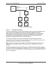
4.1.3 System Management Mode Handling
The Intel
®
E7501 MCH supports System Management Mode (SMM) operation in standard
(compatible) mode. System Management RAM (SMRAM) provides code and data storage
space for the SMI_L handler code, and is made visible to the processor only on entry to SMM,
or other conditions, which can be configured using Intel E7501 PCI registers.
4.2 I/O Map
The SE7501WV2 allows I/O addresses to be mapped to the processor bus or through
designated bridges in a multi-bridge system. Other PCI devices, including the ICH3-S, have
built-in features that support PC-compatible I/O devices and functions, which are mapped to
specific addresses in I/O space. On the SE7501WV2 server board, the ICH3-S provides the
bridge to ISA functions through the LPC bus.
4.3 Accessing Configuration Space
All PCI devices contain PCI configuration space, accessed using mechanism #1 defined in the
PCI Local Bus Specification.
If dual processors are used, only the processor designated as the Boot-strap Processor (BSP)
should perform PCI configuration space accesses. Precautions should be taken to guarantee
that only one processor performs system configuration.
When CONFIG_ADDRESS is written to with a 32-bit value (selecting the bus number, device on
the bus, and specific configuration register in the device), a subsequent read or write of
CONFIG_DATA initiates the data transfer to/from the selected configuration register. Byte
enables are valid during accesses to CONFIG_DATA; they determine whether the configuration
register is being accessed or not. Only full Dword reads and writes to CONFIG_ADDRESS are
recognized as a configuration access by the Intel chipset. All other I/O accesses to
CONFIG_ADDRESS are treated as normal I/O transactions.
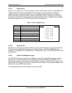
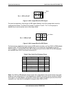
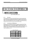
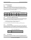
4.3.1 CONFIG_ADDRESS Register
CONFIG_ADDRESS is 32 bits wide and contains the field format shown in the following figure.
Bits [23::16] choose a specific bus in the system. Bits [15::11] choose a specific device on the
selected bus. Bits [10:8] choose a specific function in a multi-function device. Bit [8::2] select a
specific register in the configuration space of the selected device or function on the bus.