


Intel® Server Board SE7501WV2 TPS Server Management
Revision 1.0
Intel reference number C25653-001
67
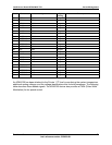
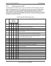
5.5.5.7 POST Code Diagnostic LEDs
To help diagnose POST failures, a set of four bi-color diagnostic LEDs is located on the back
edge of the baseboard. Each of the four LEDs can have one of four states: Off, Green, Red, or
Amber. During the POST process, each light sequence represents a specific Port-80 POST
code. If a system should hang during POST, the diagnostic LEDs will present the last test
executed before the hang. When reading the lights, the LEDs should be observed from the back
of the system. The most significant bit (MSB) is the first LED on the left, and the least significant
bit (LSB) is the last LED on the right.
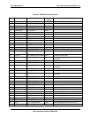
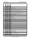
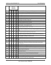
Table 25. Boot Block POST Progress Codes
Diagnostic LED
Decoder
G=Green, R=Red,
A=Amber
Hi Low
Description
10h Off Off Off R
The NMI is disabled. Start Power-on delay. Initialization code checksum
verified.
11h Off Off Off A
Initialize the DMA controller, perform the keyboard controller BAT test, start
memory refresh, and enter 4 GB flat mode.
12h Off Off G R Get start of initialization code and check BIOS header.
13h Off Off G A Memory sizing.
14h Off G Off R
Test base 512K of memory. Return to real mode. Execute any OEM patches
and set up the stack.
15h Off G Off A
Pass control to the uncompressed code in shadow RAM. The initialization code
is copied to segment 0 and control will be transferred to segment 0.
16h Off G G R
Control is in segment 0. Verify the system BIOS checksum.
If the system BIOS checksum is bad, go to checkpoint code E0h.
Otherwise, going to checkpoint code D7h.
17h Off G G A Pass control to the interface module.
18h G Off Off R Decompress of the main system BIOS failed.
19h G Off Off A Build the BIOS stack. Disable USB controller. Disable cache.
1Ah G Off G R Uncompress the POST code module. Pass control to the POST code module.
1Bh A R Off R Decompress the main system BIOS runtime code.
1Ch A R Off A Pass control to the main system BIOS in shadow RAM.
E0h R R R Off
Start of recovery BIOS. Initialize interrupt vectors, system timer, DMA controller,
and interrupt controller.
E8h A R R Off Initialize extra module if present.
E9h A R R G Initialize floppy controller.
EAh A R A Off Try to boot floppy diskette.
EBh A R A G If floppy boot fails, intialize ATAPI hardware.
ECh A A R Off Try booting from ATAPI CD-ROM drive.
EEh A A A Off Jump to boot sector.
EFh A A A G Disable ATAPI hardware.
20h Off Off R Off Uncompress various BIOS Modules
22h Off Off A Off Verify password Checksum
24h Off G R Off Verify CMOS Checksum.