


Server Management Intel® Server Board SE7501WV2 TPS
Revision 1.0
Intel reference number C25653-001
64
5.5 Error Reporting
This section documents the types of system bus error conditions monitored by the SE7501WV2
board set.
5.5.1 Error Sources and Types
One of the major requirements of server management is to correctly and consistently handle
system errors. System errors on the SE7501WV2, which can be disabled and enabled
individually, can be categorized as follows:
• PCI bus errors
• Processor bus errors
• Memory single- and multi-bit errors
• General Server Management sensors
On the SE7501WV2 platform, the general server management sensors are managed by the
Sahalee BMC.
5.5.2 PCI Bus Errors
The PCI bus defines two error pins, PERR# and SERR#, for reporting PCI parity errors and
system errors, respectively. In the case of PERR#, the PCI bus master has the option to retry
the offending transaction, or to report it using SERR#. All other PCI-related errors are reported
by SERR#. SERR# is routed to NMI if enabled by BIOS.
5.5.3 Intel
®
Xeon™ Processor Bus Errors
The MCH supports the data integrity features supported by the Xeon bus, including address,
request, and response parity. In addition, the MCH can generate BERR# on unrecoverable
errors detected on the processor bus. Unrecoverable errors are routed to an NMI by the BIOS.
5.5.4 Memory Bus Errors
The MCH is programmed to generate an SMI on single-bit or double-bit data errors in the
memory array if ECC memory is installed. The MCH performs the scrubbing. The SMI handler
records the error and the DIMM location to the system event log.
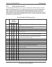
5.5.5 Fault and Status LEDs
The SE7501WV2 server board uses system fault/status LEDs in many areas of the board.
There are fault LEDs for the memory DIMMs, the fan headers, and the processors. There are
also status LEDs for 5-volt stand-by and system status indication. A blue LED is provided as a
system ID LED. When the error reporting system determines there is a problem with any device,
it will light the LED of the failing component. In the event of a power switch power down or loss
of AC, the status of all baseboard fault LEDs will be remembered and restored by BMC when
AC is restored. Fault LEDs will only be reset when a Front Panel Reset is performed with main
power available to the system or under control of an IPMI command.