


SE7501WV2 Connectors Intel® Server Board SE7501WV2 TPS
Revision 1.0
Intel reference number C25653-001
148
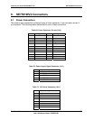
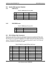
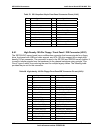
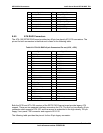
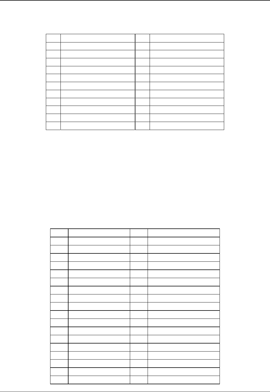
Table 79. SSI Compliant 24-pin Front Panel Connector Pinout (J1H1)
Pin Signal Name Pin Signal Name
1 Power LED Anode 2 SB5V
3 Key 4 SB5V
5 Power LED Cathode 6 Cool Fault LED
7 HDD Activity LED Anode 8 SB5V
9 HDD Activity LED Cathode 10 System Fault LED
11 Power Switch 12 NIC#1 Activity LED
13 GND (Power Switch) 14 NIC#1 Link LED
15 Reset Switch 16 I2C SDA
17 GND (Reset Switch) 18 I2C SCL
21 GND (ACPI Sleep Switch) 22 NIC#2 Activity LED
23 NMI to CPU Switch 24 NIC#2 Link LED
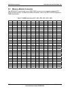
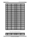
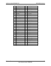
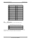
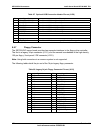
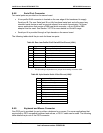
8.6.1 High Density 100-Pin Floppy / Front Panel / IDE Connector (J2G1)
The SE7501WV2 server board has a multifunction connector that houses signals for a floppy
drive, front panel with USB and video support, and ATA-100 drive support into a single high-
density 100-pin connector. The connector is used in the SR1300 and SR2300 server chassis. It
is used to transfer signals from the baseboard to the chassis backplane using a single “Flex
Circuit” type of cable, thus reducing the need for multiple legacy cables. The following table
provides the pin-out for this connector.
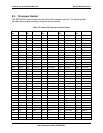
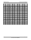
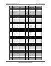
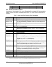
Table 80. High density 100-Pin Floppy/Front Panel/IDE Connector Pin out (J2G1)
Pin Signal Name Pin Signal Name
A1 V_Red B1 GND
A2 V_Green B2 GND
A3 V_blue B3 GND
A4 V_Vsync B4 V_Hsync
A5 FP_NMI_BTN_L B5 RJ45_SEC_ACTLED_R
A6 GND B6 RJ45_SEC_LILED_R
A7 FP_ID_BTN_L B7 FP_CHASSIS_INTRUSION
A8 GND B8 PB1_5VSB_SCL
A9 FP_RST_BTN_L B9 PB1_5VSB_SDA
A10 HDD_FAULT_R_L B10 RJ45_PRI_ACTLED_R
A11 FP_PWR_BTN_L B11 RJ45_PRI_LILED_R
A12 HDD_LED_ACT_R_L B12 FP_ID_LED_R_L
A13 VCC B13 SB5V
A14 FP_PWR_LED_R_L B14 FP_SYS_FLT_LED2_R_L
A15 SB5V B15 FP_SYS_FLT_LED_R_L
A16 RST_P6_PWR_GOOD B16 IPMB_5VSB_SCL
A17 IPMB_5VSB_SDA B17 GND
A18 GND B18 FD_HDSEL_L