


SE7501WV2 Connectors Intel® Server Board SE7501WV2 TPS
Revision 1.0
Intel reference number C25653-001
146
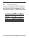
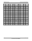
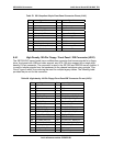
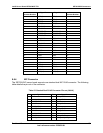
Pin Side B Side A Pin Side B Side A
48 AD[10] Ground 94 Ground Pull Down
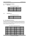
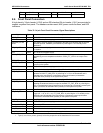
8.6 Front Panel Connectors
A high density, 34-pin header (J1G4) and an SSI standard 24-pin header (J1H1) are provided to
support a system front panel. The headers contain reset, NMI, power control buttons, and LED
indicators.
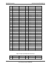
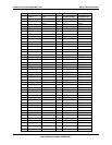
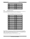
Table 78. 34-pin Front Panel Connector Signal Descriptions
Signal
Type
1
Description
SPKR_FP Out SPKR_FP is the speaker data for the front panel/chassis mounted speaker.
GROUND ground GROUND is the power supply ground.
CHASSIS_INTRU
SION
In The chassis intrusion signal is connected to the BMC and indicates that the chassis
has been opened. CHASSIS_INTRUSION is pulled high to +5 V standby on the
baseboard.
FP_HD_ACT* Out The hard drive activity signal indicates activity on one of the hard disk controllers in
the system.
+5V Power +5 V is the 5-volt power supply.
COOL_FLT_LED* Out The cooling fault LED indicates that either a fan failure has occurred or the system is
approaching an over-temperature situation. COOL_FLT_LED* is an output of the
BMC.
PWR_LED* Out Power present LED
PWR_FLT_LED* Out The system fault signal indicates either a power fault or SCSI drive failure has
occurred in the system.
GROUND ground GROUND is the power supply ground.
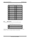
SM_HI_SDA in/out I
2
C data is the data signal for the Intelligent Platform Management Bus.
FP_NMI_BTN* In The front panel NMI is connected to a BMC input port, allowing the front panel to
generate an NMI. FP_NMI_BTN* is pulled high to +5 V on the baseboard and is
intended to be connected to a momentary-contact push button (connected to
GROUND when pushed) on the system front panel.
SM_HI_SCL in/out The I
2
C clock is the clock signal for the Intelligent Platform Management Bus.
FP_RST_BTN* In The front panel reset is connected to the BMC and causes a hard reset to occur,
resetting all baseboard devices except for the BMC. FP_RST_BTN* is pulled high to
+5V on the baseboard, and is intended to be connected to a momentary-contact push
button (connected to GROUND when pushed) on the system front panel.
+5V standby Power +5 V Standy is the standby 5-volt power supply.
FP_PWR_BTN* In The front panel power control is connected to the BMC and causes the power to
toggle (on → off, or off → on). FP_PWR_BTN* is pulled high to +5 V standby on the
baseboard and is intended to be connected to a momentary-contact push button
(connected to GROUND when pushed) on the system front panel.
SM_FP_ISOL In SM_FP_ISOL, when asserted, isolates the front panel SM bus.
GROUND ground GROUND is the power supply ground.
RJ45_ACTLED_R in NIC activity LED.
reserved – Reserved.
SM_PRI_SCL in/out The I
2
C clock is the clock signal for the primary private bus.
SM_PRI_SDA in/out I
2
C Data is the data signal for the primary private bus.
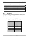
Note:
1. Type (in, out, in/out, power, ground) is from the perspective of the baseboard.I/O connectors