


Intel® Server Board SE7501WV2 TPS Functional Architecture
Revision 1.0
Intel reference number C25653-001
31
• APIC and 8259 interrupt controller
• Power management
• System RTC
• General purpose I/O
The following are the descriptions of how each supported feature is used on the SE7501WV2
server board.
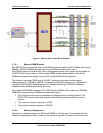
3.2.4.1 PCI Bus P32-A I/O Subsystem
The ICH3-S provides a legacy 32-bit PCI subsystem and acts as the central resource on this
PCI interface. The P32-A supports the following embedded devices and connectors:
• An ATI* Rage XL video controller with 3D/2D graphics accelerator
• Promise Technology* PDC20277 dual channel ATA-100 controller (ATA-100 board only)
3.2.4.2 PCI Bus Master IDE Interface
The ICH3-S acts as a PCI-based Ultra DMA/100 IDE controller that supports programmed I/O
transfers and bus master IDE transfers. The ICH3-S supports two IDE channels, supporting two
drives each (drives 0 and 1). The SE7501WV2 server board provides two separate interfaces to
the IDE controller. The first is a single SSI compliant 40-pin (2x20) IDE connector. The second
is through the high-density 100-pin floppy / IDE / front panel connector that is used with the
Intel
®
SR1300 and SR2300 server chassis.
The SE7501WV2 IDE interface supports Ultra DMA/100 Synchronous DMA Mode transfers on
the 40-pin connector and supports Ultra DMA/33 transfers on the 100-pin connector.
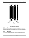
3.2.4.3 USB Interface
The ICH3-S contains three USB controllers and six USB ports. The USB controller moves data
between main memory and the six USB ports. All six ports function identically and with the
same bandwidth. The SE7501WV2 server board only supports four of the six ports on the
board.
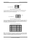
The SE7501WV2 provides two external USB ports on the back of the server board. The first
external connector is located within the standard ATX I/O panel area while the second is located
directly behind the P64-B full-length PCI card slot. The USB specification defines the external
connectors.
The third and fourth USB ports are optional and can be accessed by cabling from the internal 9-
pin connector located on the baseboard to external USB ports located either in the front or the
rear of a given chassis.
3.2.4.4 Compatibility Interrupt Control
The ICH3-S provides the functionality of two 82C59 PIC devices for ISA-compatible interrupt
handling.