


102
Selection and protection of a motor
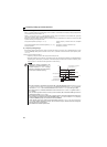
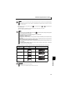
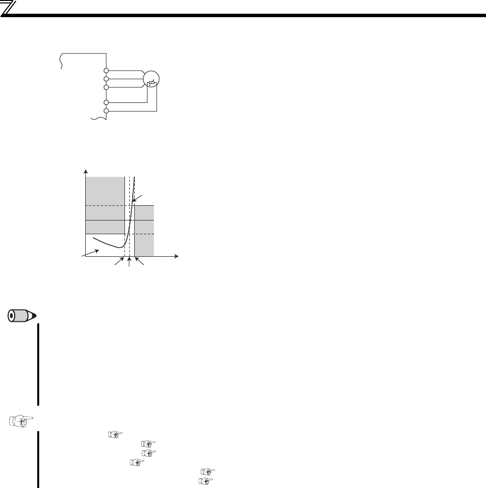
(5) PTC thermistor protection (Pr. 561)
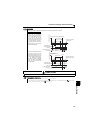
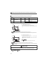
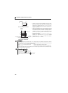
PTC thermistor input connection
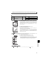
PTC thermistor characteristics
Terminal 2 and terminal 10 are available for inputting of motor
built-in PTC thermistor output. When the PTC thermistor input
reaches to the resistance value set in Pr. 561 PTC thermistor
protection level, inverter outputs PTC thermistor operation error
signal (E.PTC) and trips.
Check the characteristics of the using PTC thermistor, and set
the resistance value within a protection providing temperature
TN, just around the center of R1 and R2 in a left figure. If the Pr.
561 setting is closer to R1 or R2, the working temperature of
protection goes higher (protection works later), or lower
(protection works earlier).
PTC thermistor resistance can be displayed in operation panel,
parameter unit (FR-PU07) (Refer to page 128), or RS-485
communication (Refer to page 180) when PTC thermistor
protection is active (Pr. 561 ≠ "9999").
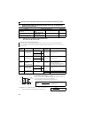
REMARKS
When using terminal 2 as PTC thermistor input (Pr. 561 ≠ "9999"), terminal 2 is not available for analog frequency command.
Also unavailable when using terminal 2 for PID control and Dancer control. When PID control and Dancer control is not active
(Pr. 128 PID action selection = "0"), terminal 4 functions as follows.
When Pr. 79 = "4" or in external operation mode ...............Terminal 4 is active whether AU signal is ON/OFF
When Pr. 79 = "3" ...............................................................Terminal 4 is active for frequency command when AU signal is ON
For the power supply terminal of PTC thermistor input, do not use power supply other than terminal 10 (external power supply,
etc). PTC thermistor does not work properly.
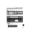
Parameters referred to
Pr. 71 Applied motor Refer to page 103
Pr. 72 PWM frequency selection Refer to page 148
Pr. 79 Operation mode selection Refer to page 165
Pr. 128 PID action selection Refer to page 212
Pr. 178 to Pr. 182 (input terminal function selection) Refer to page 113
Pr. 190, Pr. 192 (output terminal function selection) Refer to page 119
Inverter
U
V
W
10
2
Moto
r
R2
R1
Pr. 561
TN
TN+∆TTN-∆T
Thermistor
temperature
TN: Rated operational temperature
Thermistor
resistance
Thermistor curve
Temperature-resistance
existing range