


195
Communication operation and setting
4
PARAMETERS
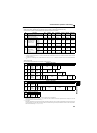
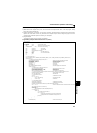
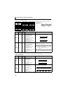
(7) Setting items and set data
After completion of parameter settings, set the instruction codes and data then start communication from the computer to
allow various types of operation control and monitoring.
No. Item
Read/
Write
Instruction
Code
Data Definition
Number of
Data Digits
(Format
)
1 Operation mode
Read H7B
H0000: Network operation
H0001: External operation
H0002: PU operation
4 digits
(B, E/D)
Write HFB
4 digits
(A, C/D)
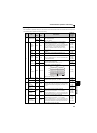
2
Monitor
Output
frequency
/speed
Read H6F
H0000 to HFFFF: Output frequency in 0.01Hz increments
Speed increments 1/0.001 (when Pr. 37 = 0.01 to 9998)
When "0.01 to 9998" is set in Pr. 37 and "01" in instruction code
HFF, the increments change to 0.001 and the data format is E2.
When "100" is set in Pr. 52, the monitor value is different
depending on whether the inverter is at a stop or running.
(Refer to page 128)
4 digits
(B, E/D),
6 digits
(B, E2/D)
Output
current
Read H70
H0000 to HFFFF: Output current (hexadecimal) in 0.01A
increments
4 digits
(B, E/D)
Output
voltage
Read H71
H0000 to HFFFF: Output voltage (hexadecimal) in 0.1V
increments
4 digits
(B, E/D)
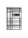
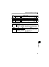
Special
monitor
Read H72
H0000 to HFFFF: Monitor data selected in instruction code HF3
When "0.01 to 9998" is set in Pr. 37 and "01" in instruction code
HFF, the data format is E2.
4 digits
(B, E/D),
6 digits
(B, E2/D)
Special
monitor
Selection No.
Read H73
H01 to H40: Monitor selection data
Refer to the special monitor No. table (page 197)
2 digits
(B, E1/D)
Write HF3
2 digits
(A1, C/D)
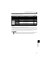
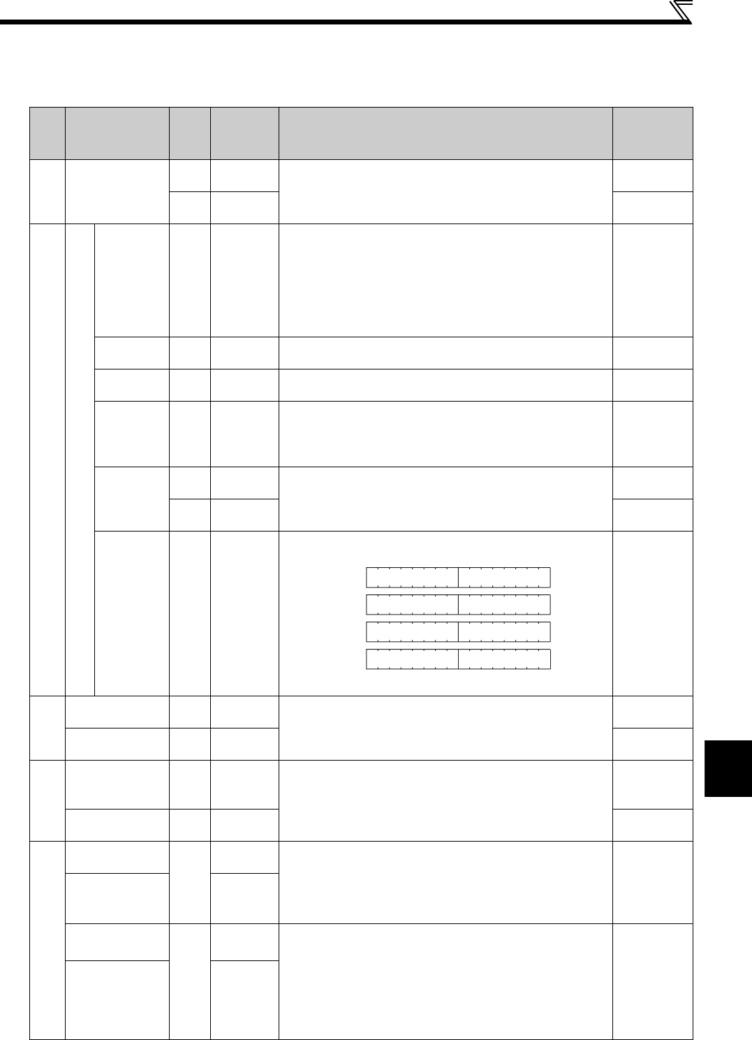
Fault
description
Read H74 to H77
H0000 to HFFFF: Two latest fault definitions
Refer to the alarm data table (page 198)
4 digits
(B, E/D)
3
Run command
(expansion)
Write HF9
Control input commands such as forward rotation signal (STF)
and reverse rotation signal (STR). (For details, refer to page 198)
4 digits
(A, C/D)
Run command Write HFA
2 digits
(A1, C/D)
4
Inverter status
monitor
(expansion)
Read H79
Monitor the states of the output signals such as forward rotation,
reverse rotation and inverter running (RUN). (For details, refer to
page 198)
4 digits
(B, E/D)
Inverter status
monitor
Read H7A
2 digits
(B, E1/D)
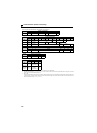
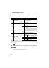
5
Set frequency
(RAM)
Read
H6D
Read set frequency/speed from RAM or EEPROM.
H0000 to HFFFF: Set frequency in 0.01Hz increments
Speed increments 1/0.001 (when Pr. 37 = 0.01 to 9998)
When "0.01 to 9998" is set in Pr. 37 and "01" in instruction code
HFF, the increments change to 0.001 and the data format is E2.
4 digits
(B, E/D),
6 digits
(B, E2/D)
Set frequency
(EEPROM)
H6E
Set frequency
(RAM)
Write
HED
Write set frequency/speed to RAM or EEPROM.
H0000 to H9C40 (0 to 400.00Hz): Frequency increments 0.01Hz
Speed increments 1/0.001 (when Pr. 37 = 0.01 to 9998)
When "0.01 to 9998" is set in Pr. 37 and "01" in instruction code
HFF, the increments change to 0.001 and the data format is A2.
To change the set frequency consecutively, write data to the
inverter RAM. (instruction code: HED)
4 digits
(A, C/D),
6 digits
(A2, C/D)
Set frequency
(RAM, EEPROM)
HEE
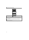
Refer to page 189 for data format (A, A1, A2, A3, B, C, C1, D, E, E1, E2, E3)
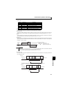
b15 b8b7 b0
Latest faultFirst fault in past
Second fault in past
Third fault in past
Fourth fault in past
Fifth fault in past
Sixth fault in past
Seventh fault in past
H74
H75
H76
H77