


198
Communication operation and setting
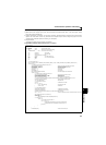
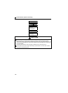
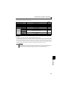
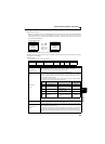
[Fault data]
Refer to page 249 for details of fault description
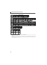
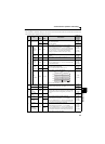
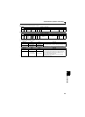
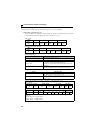
[Run command]
∗1 The signal within parentheses is the initial setting. The description changes depending on the setting of Pr. 180 to Pr. 182 (input terminal function selection) (page
113).
∗2 When Pr. 551 = "2" (PU Mode control source is PU connector), only forward rotation and reverse rotation can be used.
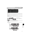
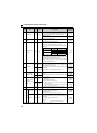
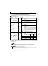
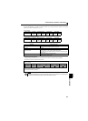
[Inverter status monitor]
∗ The signal within parentheses is the initial setting. The description changes depending on the Pr.190, Pr. 192 (output terminal function selection).
Item
Instruction
Code
Bit
Length
Description Example
Run
command
HFA 8bit
b0: AU (terminal 4 input selection) ∗2
b1: forward rotation command
b2: reverse rotation command
b3: RL (low-speed operation
command) ∗1∗2
b4: RM (middle-speed operation
command) ∗1∗2
b5: RH (high-speed operation
command) ∗1∗2
b6: RT (second function selection)∗2
b7: MRS (output stop) ∗2
Run
command
(expansion)
HF9 16bit
b0: AU (terminal 4 input selection) ∗2
b1: forward rotation command
b2: reverse rotation command
b3: RL (low-speed operation
command) ∗1∗2
b4: RM (middle-speed operation
command) ∗1∗2
b5: RH (high-speed operation
command) ∗1∗2
b6: RT (second function selection)∗2
b7: MRS (output stop) ∗1∗2
b8 to b15: —
Item
Instruction
Code
Bit
Length
Description Example
Inverter
status
monitor
H7A 8bit
b0: RUN (inverter running)
∗
b1: Forward rotation
b2: Reverse rotation
b3: SU (up-to-frequency)
b4: OL (overload)
b5: —
b6: FU (frequency detection)
b7: ABC (fault) ∗
Inverter
status
monitor
(expansion)
H79 16bit
b0: RUN (inverter running) ∗
b1: Forward rotation
b2: Reverse rotation
b3: SU (up-to-frequency)
b4: OL (overload)
b5: —
b6: FU (frequency detection)
b7: ABC (fault) ∗
b8 to b14: —
b15: Fault occurrence
For read data H3010
(Previous fault ...... THT)
(Latest fault...OC1)
0
1
0
1
0000 0 1 0000
00
b15 b8b7 b0
Latest fault
(H10)
Previous fault
(H30)
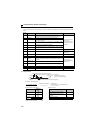
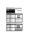
Fault definition display example (instruction code H74)
Data
Definition
H00
No fault
present
H10 E.OC1
H11 E.OC2
H12 E.OC3
H20 E.OV1
H21 E.OV2
H22 E.OV3
H30 E.THT
H31 E.THM
H40 E.FIN
H52 E.ILF
H60 E.OLT
H70 E.BE
H80 E.GF
H81 E.LF
H90 E.OHT
H91 E.PTC
Data
Definition
HB0 E.PE
HB1 E.PUE
HB2 E.RET
HC0 E.CPU
HC4 E.CDO
HC5 E.IOH
HC7 E.AIE
HC9 E.SAF
HF5 E.5
Data
Definition
00000010
b7 b0
[Example 1] H02... Forward rotation
[Example 2] H00... Stop
00000000
b7 b0
00000010
b0
[Example 1] H0002... Forward rotation
00000000
b15
00100000
b0
00000000
b15
[Example 2] H0020... Low speed operation
(When
Pr. 182 RH terminal function selection
is set to "0")
00000010
b7 b0
[Example 1] H02... During forward rotation
[Example 2] H80... Stop at fault occurrence
10000000
b7 b0
00000010
b0
00000000
b15
[Example 1] H0002... During forward rotation
10000000
b0
10000000
b15
[Example 2] H8080... Stop at fault occurrence