


228
Useful functions
4.21 Useful functions
4.21.1 Cooling fan operation selection (Pr. 244)
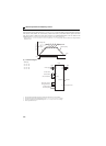
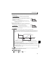
In either of the following cases, fan operation is regarded as faulty as [FN] is shown on the operation panel, and the fan fault
(FAN) and alarm (LF) signals are output.
Pr. 244 = "0"
When the fan comes to a stop with power on.
Pr. 244 = "1"
When the inverter is running and the fan stops during fan ON command.
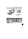
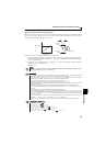
For the terminal used for FAN signal output, set "25 (positive logic) or 125 (negative logic)" to Pr. 190 or Pr. 192 (output
terminal function selection), and for the LF signal, set "98 (positive logic) or 198 (negative logic)".
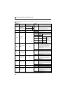
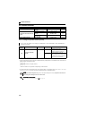
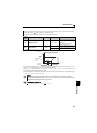
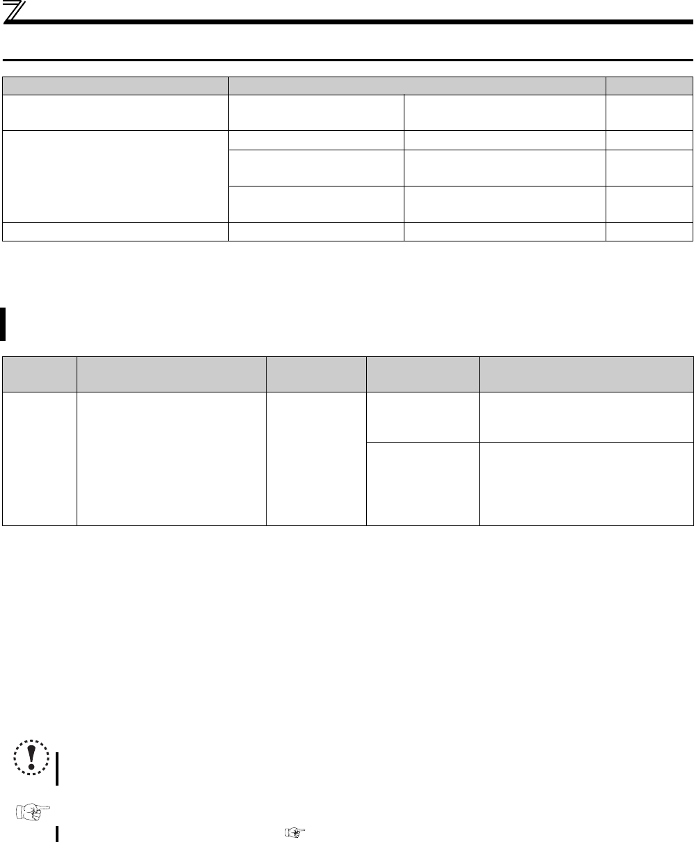
Purpose Parameter that should be Set Refer to Page
To increase cooling fan life
Cooling fan operation
selection
Pr. 244
228
To determine the maintenance time
of parts
Inverter part life display Pr. 255 to Pr. 259
229
Maintenance output
function
Pr. 503, Pr. 504
233
Current average value
monitor signal
Pr. 555 to Pr. 557
234
Freely available parameter Free parameter Pr. 888, Pr. 889
236
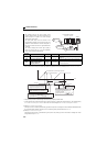
You can control the operation of the cooling fan (FR-D720-070 or more, FR-D740-036 or more, FR-D720S-070 or
more) built in the inverter.
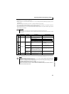
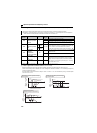
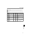
Parameter
Number
Name Initial Value Setting Range Description
244
Cooling fan operation
selection
1
0
Operates in power-on status.
Cooling fan ON/OFF control invalid (the
cooling fan is always on at power-on)
1
Cooling fan ON/OFF control valid
The fan is always on while the inverter is
running. During a stop, the inverter status
is monitored and the fan switches ON/
OFF according to the temperature.
The above parameter can be set when Pr.160 Extended function display selection = "0". (Refer to page 162)
NOTE
Changing the terminal assignment using Pr. 190, Pr. 192 (output terminal function selection) may affect the other functions.
Make setting after confirming the function of each terminal.
Parameters referred to
Pr. 190, Pr. 192 (output terminal function selection) Refer to page 119