


191
Communication operation and setting
4
PARAMETERS
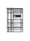
(4) Data definitions
1) Control code
2) Inverter station number
Specify the station number of the inverter which communicates with the computer.
3) Instruction code
Specify the processing request, for example, operation or monitoring, given by the computer to the inverter. Hence, the
inverter can be run and monitored in various ways by specifying the instruction code as appropriate. (Refer to page 56)
4) Data
Indicates the data such as frequency and parameters transferred to and from the inverter. The definitions and ranges of
set data are determined in accordance with the instruction codes. (Refer to page 56)
5) Waiting time
Specify the waiting time between the receipt of data at the inverter from the computer and the transmission of reply data.
Set the waiting time in accordance with the response time of the computer between 0 and 150ms in 10ms increments.
(example: 1 = 10ms, 2 = 20ms).
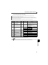
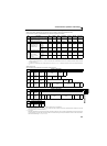
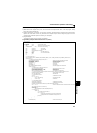
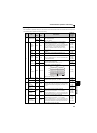
6) Sum check code
Sum check code is 2-digit ASCII (hexadecimal) representing the lower 1 byte (8 bits) of the sum (binary) derived from
the checked ASCII data.
Signal ASCII Code Description
STX H02 Start of Text (Start of data)
ETX H03 End of Text (End of data)
ENQ H05 Enquiry (Communication request)
ACK H06 Acknowledge (No data error detected)
LF H0A Line Feed
CR H0D Carriage Return
NAK H15 Negative Acknowledge (Data error detected)
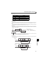
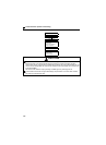
REMARKS
When the Pr. 123 PU communication waiting time setting setting is other than "9999", create the communication request data
without "waiting time" in the data format. (The number of characters decreases by 1.)
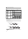
The data check time changes depending on the instruction code. (Refer to page 192)
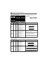
Computer
Inverter
Inverter
Computer
Inverter data processing time
=
Waiting time
(Setting 10ms)
+
Data check time
(About 10 to 30ms, which
depends on the instruction code)
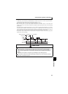
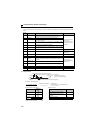
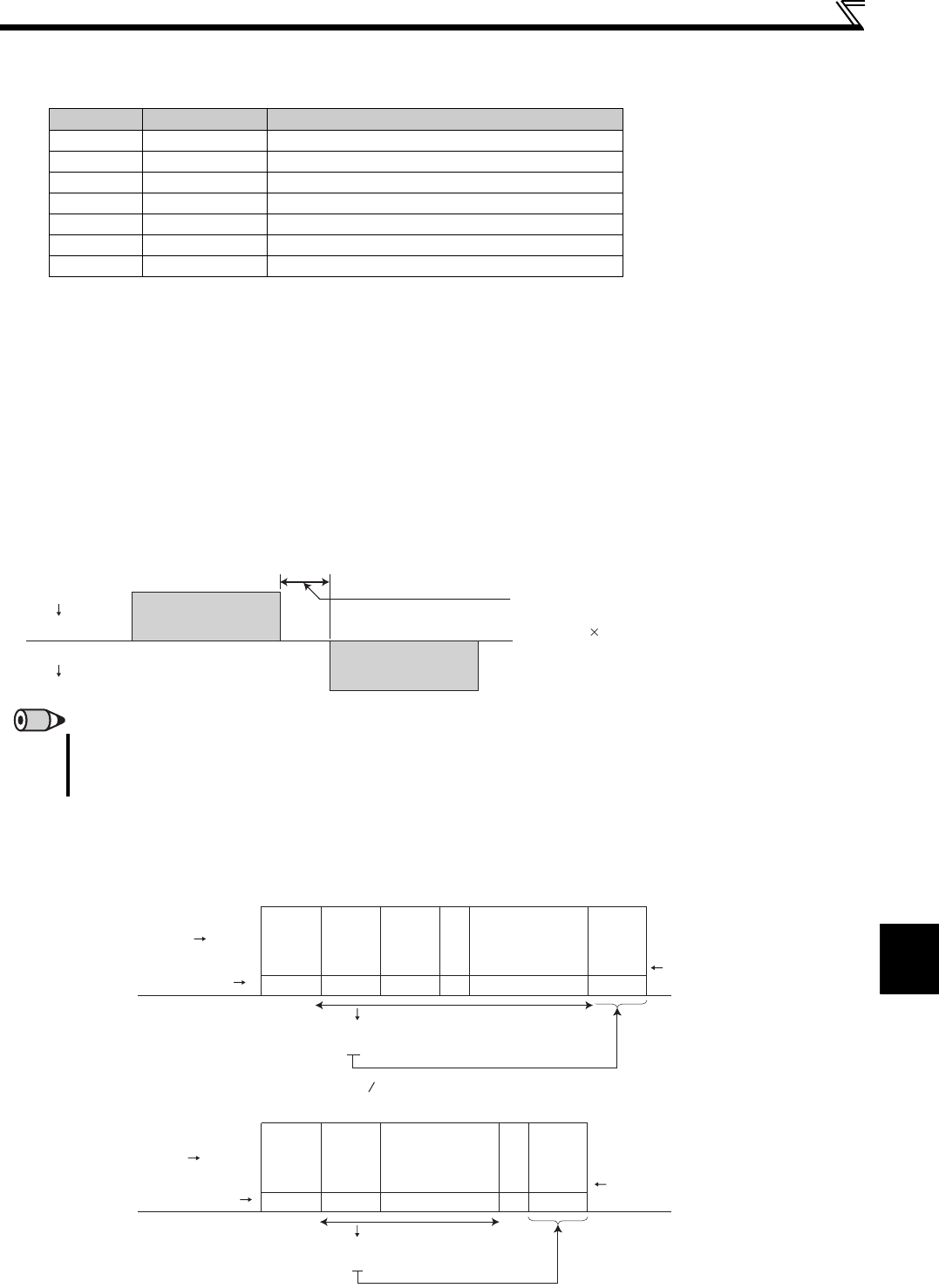
(Example 1)
Computer Inverter
ENQ
*Waiting
time
1
Instruction
code
Station
number
01
Data
E1 07ADF4
H05 H30 H31 H31H45 H31 H30 H37 H41 H44 H46 H34
(Example 2)
STX
Station
number
0117 0 30
H02 H30 H31 H37H31 H37 H30 H03 H33 H30
H30+H31+H31+H37+H37+H30
= H130
ETX
7
Inverter Computer
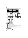
ASCII Code
ASCII Code
Sum
check
code
Sum
check
code
Binary code
Binary code
Sum
When the Pr. 123 Waiting time setting "9999", create the communication request
data without "waiting time" in the data format. (The number of characters decreases by 1.)
Sum
Data read
=
∗
H30+H31+H45+H31+H31+H30+H37+H41+H44
=H1F4