


206
Communication operation and setting
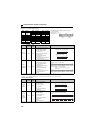
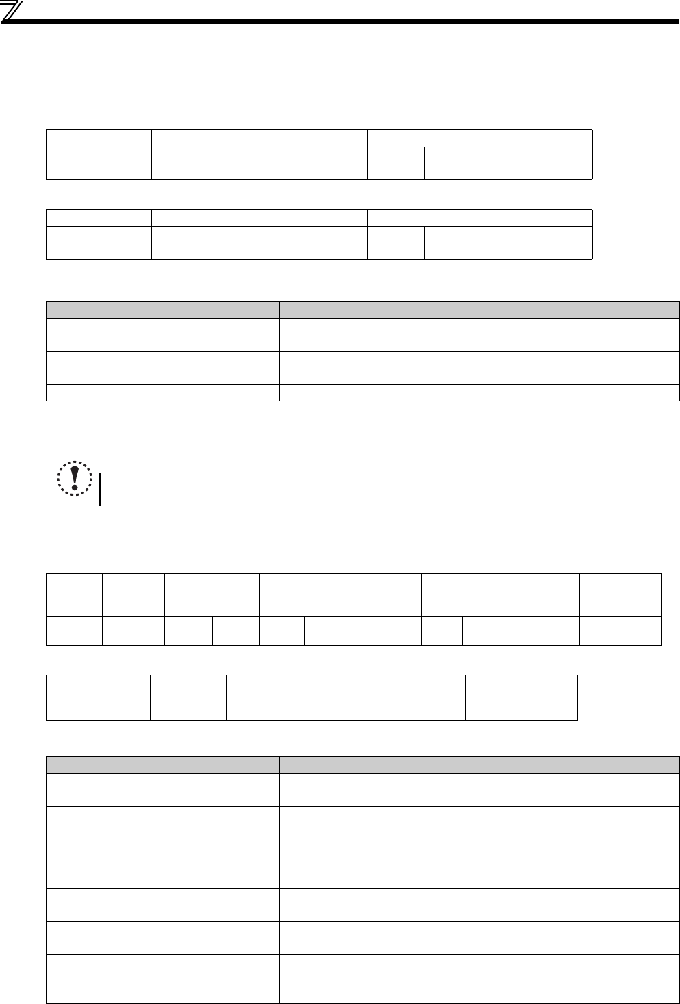
Function diagnosis (H08 or 08)
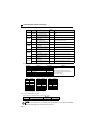
A communication check can be made since the query message sent is returned unchanged as a response message
(function of sub function code H00).
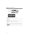
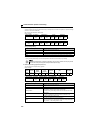
Sub function code H00 (Return Query Data)
Query message
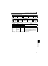
Normal response (Response message)
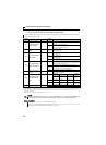
Query message setting
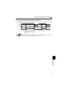
Description of normal response
1) to 4) (including CRC check) of the normal response are the same as those of the query message.
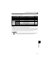
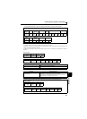
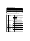
Write multiple holding register data (H10 or 16)
You can write data to multiple holding registers.
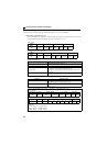
Query message
Normal response (Response message)
Query message setting
1) Slave Address 2) Function 3) Subfunction 4) Date CRC Check
(8bit)
H08
(8bit)
H00
(8bit)
H00
(8bit)
H
(8bit)
L
(8bit)
L
(8bit)
H
(8bit)
1) Slave Address 2) Function 3) Subfunction 4) Date CRC Check
(8bit)
H08
(8bit)
H00
(8bit)
H00
(8bit)
H
(8bit)
L
(8bit)
L
(8bit)
H
(8bit)
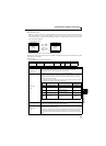
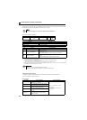
Message Setting Description
1)Slave Address
Address to which the message will be sent
Broadcast communication cannot be made (0 is invalid).
2) Function Set H08.
3)Subfunction Set H0000.
4)Data Any data can be set if it is 2 bytes long. The setting range is H0000 to HFFFF
NOTE
For broadcast communication, no response is returned in reply to a query. Therefore, the next query must be
made when the inverter processing time has elapsed after the previous query.
1)Slave
Address
2)
Function
3)
Starting
Address
4)
No. of
Registers
5)
ByteCount
6)
Data
CRC Check
(8bit)
H10
(8bit)
H
(8bit)
L
(8bit)
H
(8bit)
L
(8bit)
(8bit)
H
(8bit)
L
(8bit)
...
(n
×
2
×
8bit)
L
(8bit)
H
(8bit)
1)Slave Address 2)Function 3)Starting Address 4)No. of Registers CRC Check
(8bit)
H10
(8bit)
H
(8bit)
L
(8bit)
H
(8bit)
L
(8bit)
L
(8bit)
H
(8bit)
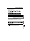
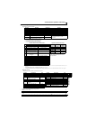
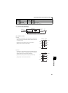
Message Setting Description
1)Slave Address
Address to which the message will be sent
Setting of address 0 enables broadcast communication
2) Function Set H10.
3)Starting Address
Address where holding register data write will be started
Starting address = Starting register address (decimal)-40001
For example, setting of the starting address 0001 reads the data of the holding
register 40002.
4) No. of Points
Number of holding registers where data will be written
The number of registers where data can be written is a maximum of 125.
5)Byte Count
The setting range is H02 to HFA (0 to 250).
Set a value twice greater than the value specified at 4).
6)Data
Set the data specified by the number specified at 4). The written data are set in
order of Hi byte and Lo byte, and arranged in order of the starting address data,
starting address + 1 data, starting address + 2 data