


34
Connection of stand-alone option unit
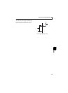
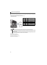
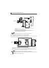
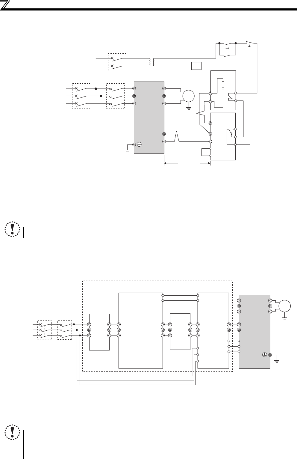
(2) Connection example with the FR-BR(-H) type resistor
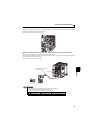
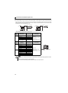
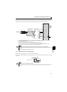
2.4.3 Connection of the high power factor converter (FR-HC)
When connecting the high power factor converter (FR-HC) to suppress power harmonics, perform wiring securely as shown
below. Incorrect connection will damage the high power factor converter and inverter.
∗1 Connect the inverter terminals (P/+ and N/-) and brake unit (FR-BU2) terminals so that their terminal names match
with each other.
(Incorrect connection will damage the inverter and brake unit.)
∗2 When the power supply is 400V class, install a step-down transformer.
∗3 The wiring distance between the inverter, brake unit (FR-BU2) and resistor unit (FR-BR) should be within
5m(16.4feet) each. Even when the wiring is twisted, the cable length must not exceed 10m(32.8feet).
∗4 Normal: across TH1-TH2...close, Alarm: across TH1-TH2...open
∗5 A jumper is connected across BUE and SD in the initial status.
NOTE
Do not remove a jumper across terminal P/+ and P1 except when connecting a DC reactor.
∗1 Always keep the power input terminals R/L1, S/L2, T/L3 open. Incorrect connection will damage the inverter.
∗2 Do not insert an MCCB between the terminals P/+ and N/- (between P and P/+, between N and N/-). Opposite polarity of terminals N/- and P/+ will
damage the inverter.
∗3 Use Pr. 178 to Pr. 182 (input terminal function selection) to assign the terminals used for the X10, RES signal. (Refer to page 113)
∗4 Be sure to connect terminal RDY of the FR-HC to the X10 signal or MRS signal assigned terminal of the inverter, and connect terminal SE of the
FR-HC to terminal SD of the inverter. Without proper connecting, FR-HC will be damaged.
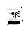
NOTE
The voltage phases of terminals R/L1, S/L2, T/L3 and terminals R4, S4, T4 must be matched.
Use sink logic (factory setting) when the FR-HC is connected. The FR-HC cannot be connected when source logic is
selected.
Do not remove a jumper across terminal P/+ and P1.
U
V
W
P/+
N/-
R/L1
S/L2
T/L3
Motor
IM
PR
N/-
BUE
SD
P/+
P
A
B
C
FR-BU2
FR-BR
TH2
TH1
PR
MCCB MC
MC
OFFON
MC
Three-phase AC
power supply
Inverter
5m or less
T
∗1
∗3
∗3
∗2
∗4
∗5
∗1
(16.4feet or less)
Inverter
High power factor converter
(FR-HC)
Outside box
(FR-HCB)
Reactor 2
(FR-HCL02)
R/L1
Reactor 1
(FR-HCL01)
Phase
detection
S/L2
T/L3
P/+
N/-
X10
RES
U
V
W
P
N
RDY
RSO
MC1
MC2
R4
S4
T4
R
S
T
R4
S4
T4
R3
S3
T3
R3
S3
T3
R2
S2
T2
R2
S2
T2
R
S
T
MC1
MC2
SD
SE
MCCB
MC
Moto
r
IM
Three-phase
AC power
supply
∗2
∗3
∗1
∗3
∗4