


235
Useful functions
4
PARAMETERS
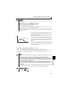
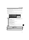
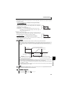
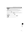
3) Setting of Pr.557 Current average value monitor signal output reference current
Set the reference (100%) for outputting the signal of the current average value. Obtain the time to output the signal from
the following calculation.
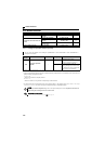
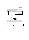
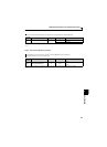
4)Setting of Pr. 503 Maintenance timer
Note that the output time range is 0.5 to 9s and the output time is either of the
following values when the output current average value is the corresponding
percentage of the Pr. 557 setting.
Less than 10% ... 0.5s, more than 180% ... 9s
Example) when Pr. 557 = 10A and the average value of output current is 15A
As 15A/10A x 5s=7.5, the current average value monitor signal is
output as low pulse shape for 7.5s.
After the output current average value is output as low pulse shape, the
maintenance timer value is output as high pulse shape. The output time of the
maintenance timer value is obtained from the following calculation.
Note that the output time range is 2 to 9s, and it is 2s when the Pr. 503 setting is
less than 16000h and 9s when exceeds 72000h.
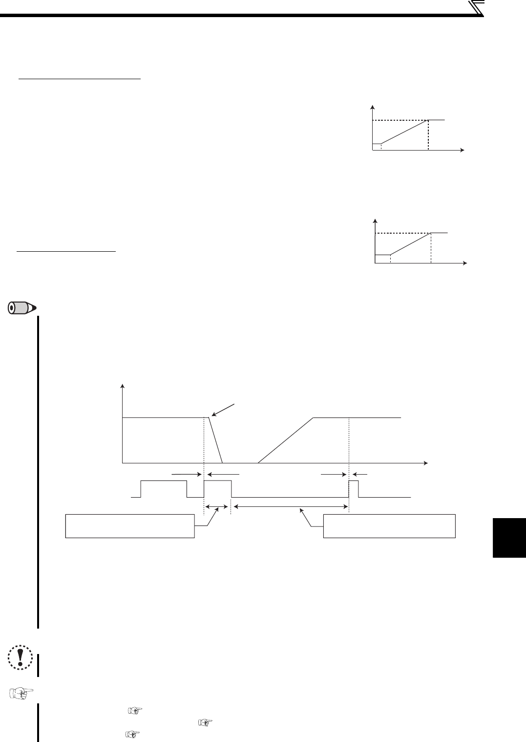
REMARKS
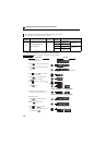
Mask of data output and sampling of output current are not performed during acceleration/deceleration.
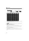
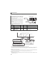
When the speed is changed to acceleration/deceleration from constant speed during start pulse output, the data is judged as
invalid. The start pulse is output as high pulse shape for 3.5s, and the end signal is output as low pulse shape for 16.5s.
The signal is output for at least 1 cycle even when acceleration/deceleration state continues after the start pulse output is
completed.
When the output current value (inverter output current monitor) is 0A on completion of the 1 cycle signal output, the signal is not
output until the speed becomes constant next time.
The current average value monitor signal (Y93) is output as low pulse shape for 20s (without data output) under the following conditions.
(a) When the motor is in the acceleration/deceleration state on completion of the 1 cycle signal output
(b) When 1-cycle signal output was ended during restart operation with the setting of automatic restart after instantaneous
power failure (Pr. 57 ≠ "9999")
(c) When restart operation was being performed at the point of data output mask end with the setting of automatic restart after
instantaneous power failure (Pr. 57 ≠ "9999")
NOTE
Changing the terminal assignment using Pr. 190, Pr. 192 (output terminal function selection) may affect the other functions.
Make setting after confirming the function of each terminal.
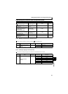
Parameters referred to
Pr. 57 Restart coasting time Refer to page 136
Pr. 190, Pr. 192 (output terminal function selection) Refer to page 119
Pr. 503 Maintenance timer
Refer to page 233
Output current average value
× 5s
(Output current average value 100%/5s)
Pr. 557 setting
9
0.5
10 (%)
(s)
Output current average value
180
Signal output time
Pr. 503 × 100
× 5s (Maintenance timer value 100%/5s)
40000h
9
2
16000
(h)
(s)
Maintenance timer value
72000
Signal output time
5) End pulse
Output as low pulse shape for 16.5s
Y93 signal
2) Start pulse
Output as high pulse shape for 3.5s
Invalid cycle (20s)
Next cycle
Time
Output frequency
The speed is changed to deceleration
from the constant speed during start pulse output
Previous cycle