


47
3
PRECAUTIONS FOR USE OF THE INVERTER
Precautions for use of the inverter
(12) Do not apply a voltage higher than the permissible voltage to the inverter I/O signal circuits.
Application of a voltage higher than the permissible voltage to the inverter I/O signal circuits or opposite polarity may
damage the I/O devices. Especially check the wiring to prevent the speed setting potentiometer from being connected
incorrectly to short terminals 10-5.
(14) If the machine must not be restarted when power is restored after a power failure, provide a magnetic contactor in the
inverter's input side and also make up a sequence which will not switch on the start signal.
If the start signal (start switch) remains on after a power failure, the inverter will automatically restart as soon as the
power is restored.
(15) Instructions for overload operation
When performing operation of frequent start/stop of the inverter, rise/fall in the temperature of the transistor element of
the inverter will repeat due to a repeated flow of large current, shortening the life from thermal fatigue. Since thermal
fatigue is related to the amount of current, the life can be increased by reducing current at locked condition, starting
current, etc. Decreasing current may increase the life. However, decreasing current will result in insufficient torque and
the inverter may not start. Therefore, choose the inverter which has enough allowance for current (up to 2 rank larger in
capacity).
(16) Make sure that the specifications and rating match the system requirements.
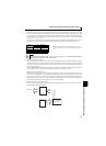
(17) When the motor speed is unstable, due to change in the frequency setting signal caused by electromagnetic noises from
the inverter, take the following measures while applying the motor speed by the analog signal.
Do not run the signal cables and power cables (inverter I/O cables) in parallel with each other and do not bundle them.
Run signal cables as far away as possible from power cables (inverter I/O cables).
Use shield cables as signal cables.
Install a ferrite core on the signal cable (Example: ZCAT3035-1330 TDK).
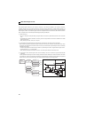
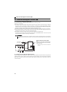
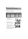
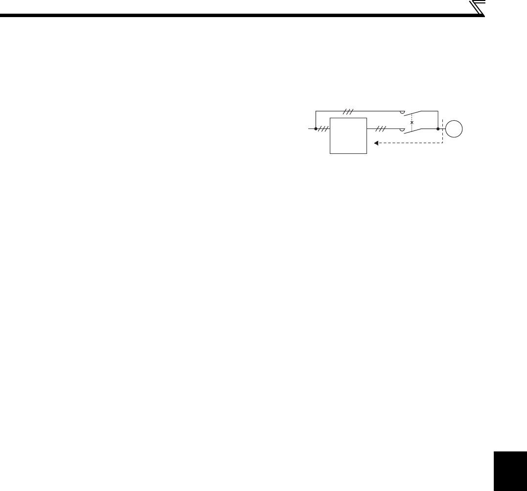
(13) Provide electrical and mechanical interlocks for MC1 and MC2
which are used for bypass operation. When the wiring is
incorrect and if there is a bypass operation circuit as shown
right, the inverter will be damaged due to arcs generated at the
time of switch-over or chattering caused by a sequence error.
Power
supply
Inverter
Undesirable current
MC2
MC1
Interlock
U
V
W
R/L1
S/L2
T/L3
IM