


197
Communication operation and setting
4
PARAMETERS
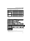
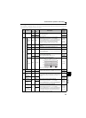
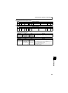
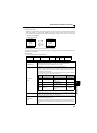
Example) When reading the C3 (Pr. 902) and C6 (Pr. 904) settings from the inverter of station 0
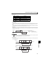
To read/write C3 (Pr. 902) and C6 (Pr. 904) after inverter reset or parameter clear, execute from 1) again.
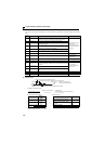
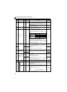
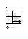
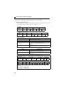
List of calibration parameters
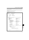
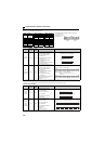
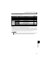
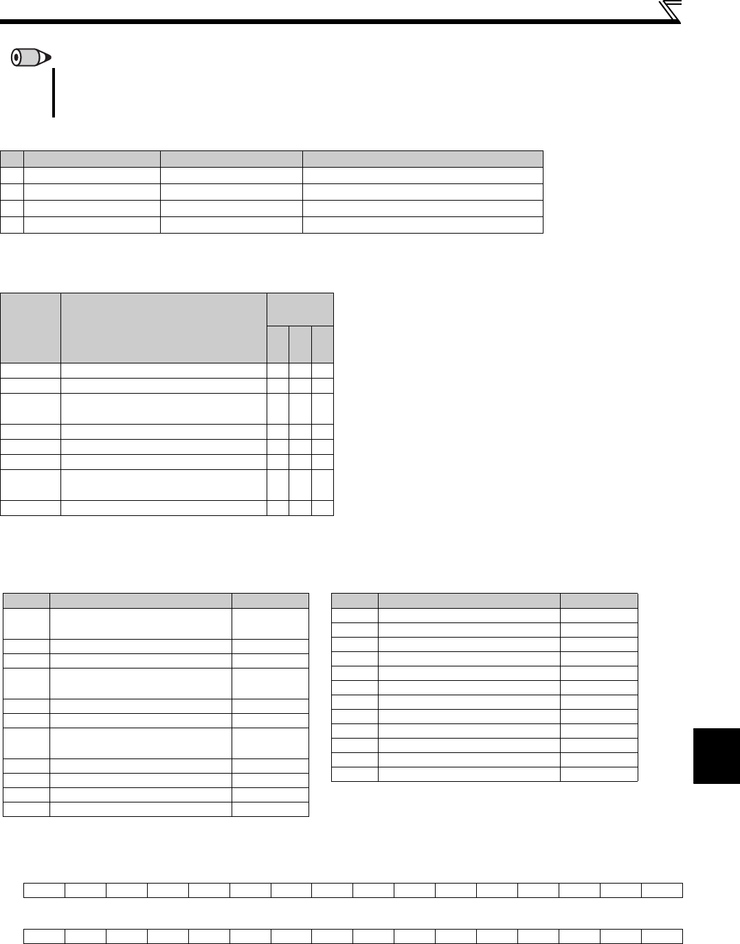
[Special monitor selection No.]
Refer to page 128 for details of the monitor description.
∗1 When "0.01 to 9998" is set in Pr. 37 and "01" in instruction code HFF, the data format is 6 digits (E2).
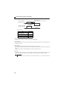
∗2 Input terminal monitor details
∗3 Output terminal monitor details
REMARKS
Set 65520 (HFFF0) as a parameter value "8888" and 65535 (HFFFF) as "9999".
For the instruction codes HFF, HEC and HF3, their values are held once written but cleared to zero when an inverter reset or all
clear is performed.
Computer Send Data Inverter Send Data Description
1)
ENQ 00 FF 0 01 82 ACK 00 Set "H01" to the expansion link parameter.
2)
ENQ 00 EC 0 01 7E ACK 00 Set "H01" to second parameter changing.
3)
ENQ 00 5E 0 0F STX 00 0000 ETX 25 C3 (Pr. 902) is read. 0% is read.
4)
ENQ 00 60 0 FB STX 00 0000 ETX 25 C6 (Pr. 904) is read. 0% is read.
b15 b0
—————————RHRMRL——STRSTF
b15 b0
——————————ABC————RUN
Parameter
Name
Instruction
Code
Read
Write
Extended
C2 (902)
Terminal 2 frequency setting bias frequency
5E DE 1
C3 (902) Terminal 2 frequency setting bias
5E DE 1
125 (903)
Terminal 2 frequency setting gain
frequency
5F DF 1
C4 (903) Terminal 2 frequency setting gain
5F DF 1
C5 (904)
Terminal 4 frequency setting bias frequency
60 E0 1
C6 (904) Terminal 4 frequency setting bias
60 E0 1
126 (905)
Terminal 4 frequency setting gain
frequency
61 E1 1
C7 (905) Terminal 4 frequency setting gain
61 E1 1
Data Description Unit
H01 Output frequency/speed ∗1
0.01Hz/
0.001
H02 Output current 0.01A
H03 Output voltage 0.1V
H05 Frequency setting/speed setting ∗1
0.01Hz/
0.001
H08 Converter output voltage 0.1V
H09 Regenerative brake duty 0.1%
H0A
Electronic thermal relay function
load factor
0.1%
H0B Output current peak value 0.01A
H0C Converter output voltage peak value 0.1V
H0E Output power
0.01kW
H0F Input terminal status ∗2
—
H10 Output terminal status ∗3
—
H14 Cumulative energization time
1h
H17 Actual operation time
1h
H18 Motor load factor
0.1%
H19 Cumulative power
1kWh
H34 PID set point
0.1%
H35 PID measured value
0.1%
H36 PID deviation
0.1%
H3D Motor thermal load factor
0.1%
H3E Inverter thermal load factor
0.1%
H3F Cumulative power 2
0.01kWh
H40 PTC thermistor resistance
0.01k
Ω
Data Description Unit