


273
Measurement of main circuit voltages, currents and powers
6
PRECAUTIONS FOR MAINTENANCE AND INSPECTION
6.2.1 Measurement of powers
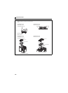
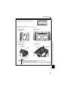
Using an electro-dynamometer type meter, measure the power in both the input and output sides of the inverter using the two-
or three-wattmeter method. As the current is liable to be imbalanced especially in the input side, it is recommended to use the
three-wattmeter method.
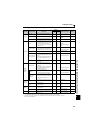
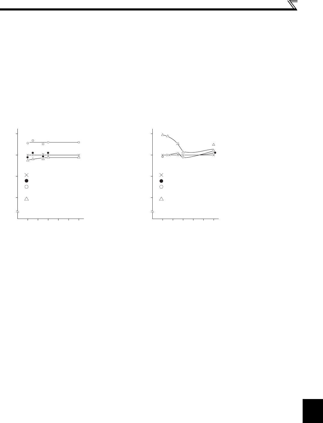
Examples of process value differences produced by different measuring meters are shown below.
An error will be produced by difference between measuring instruments, e.g. power calculation type and two- or three-
wattmeter type three-phase wattmeter. When a CT is used in the current measuring side or when the meter contains a PT on
the voltage measurement side, an error will also be produced due to the frequency characteristics of the CT and PT.
6.2.2 Measurement of voltages and use of PT
(1) Inverter input side
As the input side voltage has a sine wave and it is extremely small in distortion, accurate measurement can be made with an
ordinary AC meter.
(2) Inverter output side
Since the output side voltage has a PWM-controlled rectangular wave, always use a rectifier type voltmeter. A needle type
tester can not be used to measure the output side voltage as it indicates a value much greater than the actual value. A
moving-iron type meter indicates an effective value which includes harmonics and therefore the value is larger than that of the
fundamental wave. The value monitored on the operation panel is the inverter-controlled voltage itself. Hence, that value is
accurate and it is recommended to monitor values using the operation panel.
(3) PT
No PT can be used in the output side of the inverter. Use a direct-reading meter. (A PT can be used in the input side of the
inverter.)
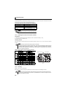
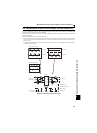
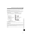
[Measurement conditions]
Constant-torque (100%) load, note that 60Hz or
more should be constantly output 3.7kW, 4-pole
motor, value indicated in 3-wattmeter method is 100%.
Example of
Measuring Inverter Input Power
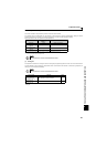
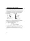
[Measurement conditions]
Constant-torque (100%) load, note that 60Hz or
more should be constantly output 3.7kW, 4-pole
motor, value indicated in 3-wattmeter method is 100%.
Example of
Measuring Inverter Output Power
3-wattmeter method (Electro-dynamometer type)
2-wattmeter method (Electro-dynamometer type)
Clip AC power meter
(For balanced three-phase load)
Clamp-on wattmeter
(Hall device power arithmetic type)
0 20 40 60 80 100120Hz
60
80
100
120
%
3-wattmeter method (Electro-dynamometer type)
2-wattmeter method (Electro-dynamometer type)
Clip AC power meter
(For balanced three-phase load)
Clamp-on wattmeter
(Hall device power arithmetic type)
0 20 40 60 80 100120Hz
60
80
100
120
%