


203
Communication operation and setting
4
PARAMETERS
(4) Message frame (protocol)
Communication method
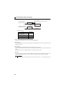
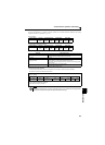
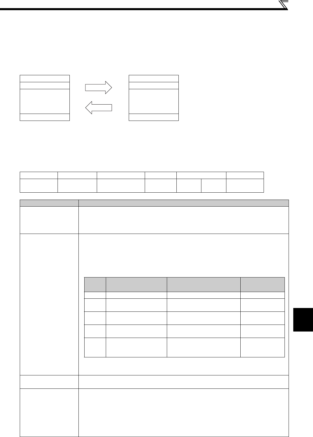
Basically, the master sends a query message (question) and the slave returns a response message (response).
When communication is normal, Device Address and Function Code are copied as they are, and when
communication is abnormal (function code or data code is illegal), bit 7 (= 80h) of Function Code is turned on and the
error code is set to Data Bytes.
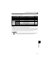
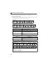
The message frame consists of the four message fields as shown above.
By adding the no-data time (T1: Start, End) of 3.5 characters to the beginning and end of the message data, the slave
recognizes it as one message.
Protocol details
The four message fields will be explained below.
Query message from Master
Device Address Device Address
Function Code Function Code
Eight-Bit
Data Bytes
Eight-Bit
Data Bytes
Error Check Error Check
Response message from slave
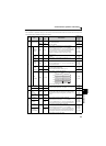
Start 1) ADDRESS 2) FUNCTION 3) DATA 4) CRC CHECK End
T1 8bit 8bit n×8bit
L
8bit
H
8bit
T1
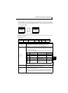
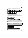
Message Field Description
1)ADDRESS field
The address code is 1 byte long (8 bits) and any of 0 to 247 can be set. Set 0 to send a broadcast
message (all-address instruction) or any of 1 to 247 to send a message to each slave.
When the slave responds, it returns the address set from the master.
The value set to Pr. 117 PU communication station number is the slave address.
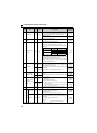
2)FUNCTION
field
The function code is 1 byte long (8 bits) and any of 1 to 255 can be set. The master sets the function
that it wants to request to the slave, and the slave performs the requested operation. The following
table gives the supported function codes. An error response is returned if the set function code is
other than those in the following table.
When the slave returns a normal response, it returns the function code set by the master. When the
slave returns an error response, it returns H80 + function code.
3)DATA field
The format changes depending on the function code (Refer to page 204). Data includes the byte count,
number of bytes, description of access to the holding register, etc.
4)CRC CHECK
field
The received message frame is checked for error. CRC check is performed, and 2 byte long data is
added to the end of the message. When CRC is added to the message, the low-order byte is added
first and is followed by the high-order byte.
The CRC value is calculated by the sending side that adds CRC to the message. The receiving side
recalculates CRC during message receiving, and compares the result of that calculation and the
actual value received in the CRC CHECK field. If these two values do not match, the result is defined
as error.
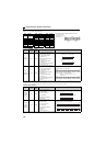
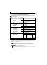
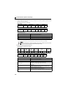
Code Function Name Outline
Broadcast
Communication
H03 Read Holding Register Reads the holding register data. Disallowed
H06 Preset Single Register
Writes data to the holding
register.
Allowed
H08 Diagnostics
Function diagnosis
(communication check only)
Disallowed
H10 Preset Multiple Registers
Writes data to multiple
consecutive holding registers.
Allowed
H46
Read Holding Register
Access Log
Reads the number of registers
that succeeded in communication
last time.
Disallowed
Table 1:Function code list