


175
Selection of operation mode and operation location
4
PARAMETERS
4.18.2 Operation mode at power-on (Pr. 79, Pr. 340)
(1) Specify operation mode at power-on (Pr. 340)
Depending on the Pr. 79 and Pr. 340 settings, the operation mode at power-on (reset) changes as described below.
When power is switched on or when power comes back on after instantaneous power failure, the inverter can be
started up in the network operation mode.
After the inverter has started up in the network operation mode, parameter write and operation can be performed from
a program.
Set this mode for communication operation using PU connector.
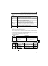
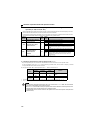
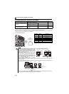
Parameter
Number
Name Initial Value Setting Range Description
79 Operation mode selection
0 0 to 4, 6, 7
Operation mode selection
(Refer to page 168)
340 ∗
Communication startup
mode selection
0
0 As set in Pr. 79.
1 Network operation mode
10
Network operation mode
Operation mode can be changed between
the PU operation mode and network
operation mode from the operation panel.
The above parameters can be changed during a stop in any operation mode.
* The above parameters can be set when
Pr. 160 Extended function display selection = "0". (Refer to page 162)
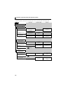
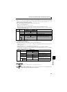
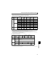
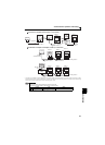
Pr. 340
Setting
Pr. 79
Setting
Operation Mode at Power-on, Power
Restoration, Reset
Operation Mode Switching
0
(initial
value)
0
(initial
value)
External operation mode
Switching among the external, PU and Net operation mode is
enabled ∗1
1 PU operation mode Fixed to PU operation mode
2 External operation mode
Switching between the external and NET operation mode is enabled
Switching to PU operation mode disabled
3, 4 External/PU combined mode Operation mode switching disabled
6 External operation mode
Switching among the external, PU, and NET operation mode is
enabled while running.
7
X12 (MRS) signal ON ....External operation
mode
Switching among the external, PU and Net operation mode is
enabled ∗1
X12 (MRS) signal OFF ...External operation
mode
Fixed to external operation mode (Forcibly switched to external
operation mode.)
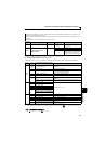
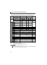
1
0
NET operation mode
Same as when Pr. 340 = "0"
1 PU operation mode
2
NET operation mode
3, 4 External/PU combined mode
6 NET operation mode
7
X12 (MRS) signal ON .......NET operation
mode
X12(MRS) signal OFF.......External operation
mode
10
0
NET operation mode Switching between the PU and Net operation mode is enabled ∗2
1 PU operation mode Same as when Pr. 340 = "0"
2 NET operation mode Fixed to NET operation mode
3, 4 External/PU combined mode Same as when Pr. 340 = "0"
6
NET operation mode
Switching between the PU and NET operation mode is enabled
while running ∗2
7 External operation mode Same as when Pr. 340 = "0"
∗1 Operation mode can not be directly changed between the PU operation mode and network operation mode
∗2 Operation mode can be changed between the PU operation mode and network operation mode with key of the operation panel and X65 signal.
Parameters referred to
Pr. 79 Operation mode selection Refer to page 165