


222
Special operation and frequency control
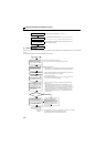
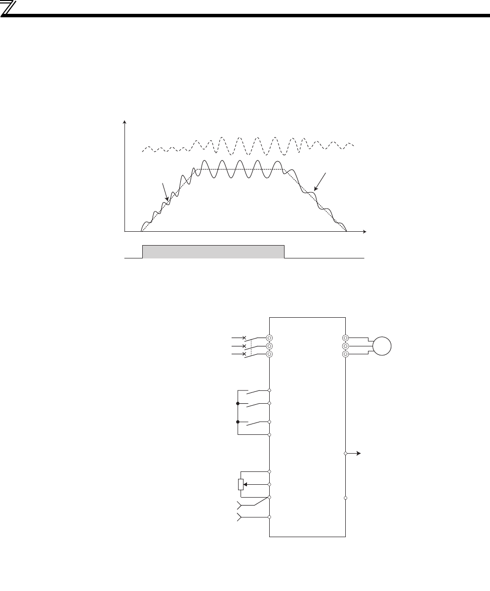
(2) Dancer control overview
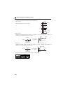
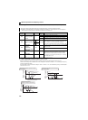
Performs dancer control by setting 40 to 43 in Pr. 128 PID action selection.The main speed command is the speed command of
each operation mode (external, PU, communication). Performs PID control by the position detection signal of the dancer
roller, then the result is added to the main speed command. For acceleration/deceleration of the main speed, set the
acceleration time in Pr. 44 Second acceleration/deceleration time/Pr. 45 Second deceleration time.
* Set 0s normally to Pr. 7 Acceleration time and Pr.8 Deceleration time. When the Pr. 7 and Pr. 8 setting is large, response of dancer control during acceleration/
deceleration is slow.
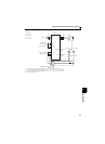
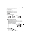
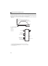
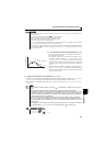
(3) Connection diagram
Sink logic
Pr. 128 = 41
Pr. 182 = 14
Pr. 190 = 15
Pr. 192 = 16
∗1 The main speed command differs according to each operation mode (external, PU, communication)
∗2 The used output signal terminal changes depending on the Pr. 190, Pr. 192 (output terminal selection) setting.
∗3 The used input signal terminal changes depending on the Pr. 178 to Pr. 182(input terminal selection) setting.
∗4 The AU signal need not be input.
STF
PID adding value
Main speed
ON
Output frequency
Time
Output frequency
Power supply
MCCB
Inverter
Forward rotation
Reverse rotation
PID control selection
Main speed commnad
setting potentiometer
*1
R/L1
S/L2
T/L3
STF
STR
RH(X14)
*3
SD
10
2
5
4
*4
U
V
W
*2 (FUP)RUN
SE
Motor
IM
Upper limit
Output signal common
Feedback value of
dancer roll position