


129
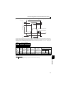
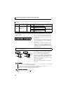
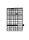
Monitor display and monitor output signal
4
PARAMETERS
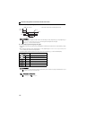
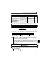
Regenerative brake
duty
0.1% 9 ∗1 9 Pr. 70 Brake duty set in Pr. 30, Pr. 70
Electronic thermal
relay function load
factor
0.1% 10 ∗1 10 100%
Displays the thermal cumulative value on
the assumption that the thermal operation
level is 100% (Larger thermal between the
motor thermal and transistor thermal). ∗6
Output current peak
value
0.01A 11 ∗1 11 Pr. 56
Holds and displays the peak value of the
output power monitor.
(Cleared at every start)
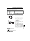
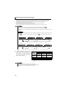
Converter output
voltage peak value
0.1V 12 ∗1 12
200V class 400V
Holds and displays the peak value of the
DC bus voltage value.
(Cleared at every start)
400V class 800V
Output power 0.01kW 14 ∗1 14
Rated inverter
power × 2
Displays the power on the inverter output
side
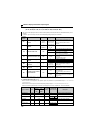
Input terminal status —
—
∗1 × —
Displays the input terminal ON/OFF status
on the operation panel.
(Refer to page 131)
Output terminal
status
— ∗1 × —
Displays the output terminal ON/OFF
status on the operation panel.
(Refer to page 131)
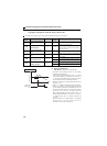
Cumulative
energization time ∗2
1h 20 × —
Adds up and displays the energization time
after inverter shipment.
You can check the numbers of the monitor
value exceeded 65535h with Pr. 563.
Reference voltage
output
—— 21—
Terminal AM:
Output 10V
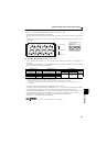
Actual operation time
∗2, ∗3
1h 23 × —
Adds up and displays the inverter operation
time.
You can check the numbers of the monitor
value exceeded 65535h with Pr. 564.
Can be cleared by Pr. 171. (Refer to page
132)
Motor load factor 0.1% 24 24 200%
Displays the output current value on the
assumption that the inverter rated current
value is 100%.
Monitor value = output power monitor
value/rated inverter current 100 [%]
Cumulative power ∗5
0.01kWh
∗4 25 × —
Adds up and displays the power amount
based on the output power monitor.
Can be cleared by Pr. 170. (Refer to page
131)
PID set point 0.1% 52 52 100%
Displays the set point, measured value and
deviation during PID control (Refer to page
217 for details)
PID measured value 0.1% 53 53 100%
PID deviation 0.1% 54 × —
Inverter I/O terminal
monitor
—55 ×× —
Displays the ON/OFF status of the inverter
input terminal and output terminal on the
operation panel (Refer to page 131 for
details)
Motor thermal load
factor
0.1% 61 61
Thermal relay
operation level
(100%)
Motor thermal heat cumulative value is
displayed.
(Motor overload trip (E.THM) at 100%)
Inverter thermal load
factor
0.1% 62 62
Thermal relay
operation level
(100%)
Transistor thermal heat cumulative value is
displayed.
(Inverter overload trip (E.THT) at 100%)
PTC thermistor
resistance
0.01kΩ 64 × —
Displays the PTC thermistor resistance at
terminal 2 when PTC thermistor protection
is active.
(0.10kΩ to 31.5kΩ) (Refer to page 100)
Types of Monitor Unit
Pr. 52 Setting
Pr.158 (AM)
Setting
Terminal AM
Full Scale Value
Description
Operation
panel
LED
PU
main
monitor