


219
Special operation and frequency control
4
PARAMETERS
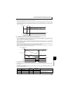
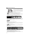
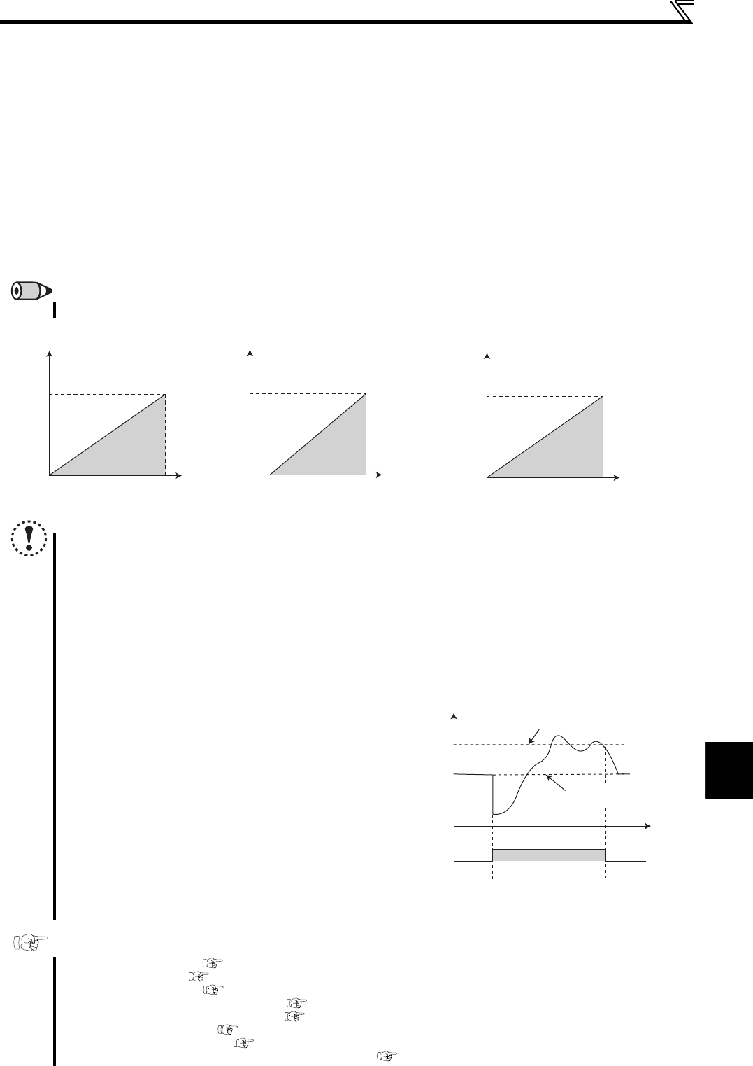
<Set point input calibration>
1. Apply the input voltage of 0% set point setting (e.g. 0V) across terminals 2-5.
2. Enter in C2 (Pr. 902) the frequency which should be output by the inverter at the deviation of 0% (e.g. 0Hz).
3. In C3 (Pr.902), set the voltage value at 0%.
4. Apply the voltage of 100% set point (e.g. 5V) across terminals 2-5.
5. Enter in Pr.125 the frequency which should be output by the inverter at the deviation of 100% (e.g. 60Hz).
6. In C4 (Pr.903), set the voltage value at 100%.
<Measured value calibration>
1. Apply the input current of 0% measured value (e.g. 4mA) across terminals 4-5.
2. Make calibration using C6 (Pr. 904).
3. Apply the input current of 100% measured value (e.g. 20mA) across terminals 4-5.
4. Make calibration using C7 (Pr. 905).
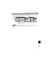
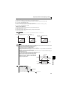
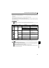
The results of the above calibration are as shown below:
REMARKS
The frequency set in C5 (Pr. 904) and Pr. 126 should be the same as set in C2 (Pr. 902) and Pr. 125 .
NOTE
If the multi-speed (RH, RM, RL, REX signal) or Jog operation (JOG signal) is entered with the X14 signal ON, PID
control is stopped and multi-speed or Jog operation is started.
If the setting is as follows, PID control becomes invalid.
Pr. 79 Operation mode selection ="6" (switchover mode)
The inverter is at a stop with Pr. 261 Power failure stop selection selected.
Changing the terminal function using any of Pr. 178 to Pr. 182, Pr. 190, Pr. 192 may affect the other functions. Make
setting after confirming the function of each terminal.
When PID control is selected, the minimum frequency is the frequency set in Pr. 902 and the maximum frequency is
the frequency set in Pr. 903.
(Pr. 1 Maximum frequency and Pr. 2 Minimum frequency settings are also valid.)
The remote operation function is invalid during PID operation.
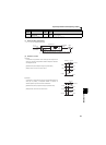
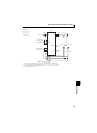
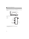
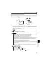
When the control is switched to PID control during normal
operation, the frequency command value calculated by PID
operation using 0Hz as standard is used without the
frequency during the operation.
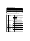
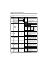
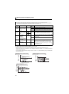
Parameters referred to
Pr. 59 Remote function selection Refer to page 93
Pr. 73 Analog input selection Refer to page 150
Pr. 79 Operation mode selection Refer to page 165
Pr. 178 to Pr. 182 (input terminal function selection) Refer to page 113
Pr. 190, Pr. 192 (output terminal function selection) Refer to page 119
Pr. 261 Power failure stop selection Refer to page 142
Pr. 561 PTC thermistor protection level
Refer to page 100
C2 (Pr. 902) to C7 (Pr. 905) Frequency setting voltage (current) bias/gain Refer to page 153
100
0
0 5 (V)
(%)
[Set point setting]
100
0
020
(mA)
(%)
[Measured value]
4
60
0
0 100
Deviation (%)
[Manipulated variable]
Manipulated
variable (Hz)
PID action
Frequency
command
PID set point
Frequency command
during normal operation
ON
Operation when control is switched to PID control
during normal operation
PID operation
Normal
operation
Normal
operation