


280
Common specifications
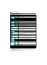
7.2 Common specifications
Control specifications
Control method
Soft-PWM control/high carrier frequency PWM control (V/F control, General-purpose magnetic flux vector control,
Optimum excitation control can be selected)
Output frequency range
0.2 to 400Hz
Frequency setting
resolution
Analog input
0.06Hz/60Hz (terminal2, 4: 0 to 10V/10bit)
0.12Hz/60Hz (terminal2, 4: 0 to 5V/9bit)
0.06Hz/60Hz (terminal4: 0 to 20mA/10bit)
Digital input
0.01Hz
Frequency
accuracy
Analog input
Within ±1% of the max. output frequency (25°C ±10°C)
Digital input
Within 0.01% of the set output frequency
Voltage/frequency characteristics
Base frequency can be set from 0 to 400Hz. Constant torque/variable torque pattern can be selected
Starting torque
150% or more (at 1Hz)...when General-purpose magnetic flux vector control and slip compensation is set
Torque boost
Manual torque boost
Acceleration/deceleration time setting
0.1 to 3600s (acceleration and deceleration can be set individually), linear or S-pattern acceleration/deceleration
mode can be selected.
Braking torque
Regenerative∗1
FR-D720-008 and 014, FR-D720S-008 and 014 ... 150%, FR-D720-025 and 042, FR-D740-012 and 022, FR-
D720S-025 and 042 ... 100%, FR-D720-070, FR-D740-036, FR-D720S-070 ... 50%, FR-D720-100 or more, FR-
D740-050 or more, FR-D720S-100 ... 20%
DC injection
brake
Operation frequency (0 to 120Hz), operation time (0 to 10s), operation voltage (0 to 30%) variable
Stall prevention operation level
Operation current level can be set (0 to 200% adjustable), whether to use the function or not can be selected
Operation specifications
Frequency setting
signal
Analog input
Two points
Terminal 2: 0 to 10V, 0 to 5V can be selected
Terminal 4: 0 to 10V, 0 to 5V, 4 to 20mA can be selected
Digital input
Entered from operation panel and parameter unit. Frequency setting increments is selectable
Start signal
Forward and reverse rotation or start signal automatic self-holding input (3-wire input) can be selected.
Input signal
Five points
You can select from among multi-speed selection, remote setting, second function selection, terminal 4 input
selection, JOG operation selection, PID control valid terminal, external thermal input, PU-external operation
switchover, V/F switchover, output stop, start self-holding selection, forward rotation, reverse rotation command,
inverter reset, PU-NET operation switchover, external-NET operation switchover, command source switchover,
inverter operation enable signal, and PU operation external interlock
Operational functions
Maximum/minimum frequency setting, frequency jump operation, external thermal relay input selection, automatic
restart after instantaneous power failure operation, forward/reverse rotation prevention, remote setting, second
function, multi-speed operation, regeneration avoidance, slip compensation, operation mode selection, offline
auto tuning function, PID control, computer link operation (RS-485), Optimum excitation control, power failure
stop, speed smoothing control, Modbus-RTU
Output signal
Output signal
points
Open collector
output
One point
Relay output
One point
Operating status
You can select from among inverter operation, up-to-frequency, overload alarm, output frequency detection,
regenerative brake prealarm, electronic thermal relay function prealarm, inverter operation ready, output current
detection, zero current detection, PID lower limit, PID upper limit, PID forward/reverse rotation output, fan
alarm∗3, heatsink overheat pre-alarm, deceleration at an instantaneous power failure, PID control activated, PID
output interruption, during retry, life alarm, current average value monitor, remote output, alarm output, fault
output, fault output 3, and maintenance timer alarm
For meter
Output points
Analog output
0 to 10VDC: one point
For meter
You can select from among output frequency, output current (steady), output voltage, frequency setting, converter
output voltage, regenerative brake duty, electronic thermal relay function load factor, output current peak value,
converter output voltage peak value, reference voltage output, motor load factor, PID set point, PID measured
value, output power, PID deviation, motor thermal load factor, inverter thermal load factor
0 to 10VDC
Indication
Operation panel
Parameter unit
(FR-PU07)
Operating status
You can select from among output frequency, output current (steady), output voltage, frequency setting,
cumulative energization time, actual operation time, converter output voltage, regenerative brake duty, electronic
thermal relay function load factor, output current peak value, converter output voltage peak value, motor load
factor, PID set point, PID measured value, PID deviation, inverter I/O terminal monitor, output power, cumulative
power, motor thermal load factor, inverter thermal load factor, PTC thermistor resistance.
Fault definition
Fault definition is displayed when the fault occurs and the past 8 fault definitions (output voltage/current/
frequency/cumulative energization time right before the fault occurs) are stored
Additional display
by the parameter
unit (FR-PU04/FR-
PU07) only
Operating status
Not used
Fault definition
Output voltage/current/frequency/cumulative energization time immediately before the fault occurs
Interactive
guidance
Function (help) for operation guide
Protective/warning
function
Protective
functions
Overcurrent during acceleration, overcurrent during constant speed, overcurrent during deceleration, overvoltage
during acceleration, overvoltage during constant speed, overvoltage during deceleration, inverter protection
thermal operation, motor protection thermal operation, heatsink overheat, input phase loss∗5 ∗6, output side earth
(ground) fault overcurrent at start∗5, output phase loss, external thermal relay operation ∗5, PTC thermistor
operation∗5, parameter error, PU disconnection, retry count excess ∗5, CPU fault, brake transistor alarm, inrush
resistance overheat, analog input error, stall prevention operation, output current detection value exceeded ∗5,
safety circuit fault
Warning
functions
Fan alarm∗3, overcurrent stall prevention, overvoltage stall prevention, PU stop, parameter write error,
regenerative brake prealarm ∗5, electronic thermal relay function prealarm, maintenance output ∗5, undervoltage,
operation panel lock, password locked, inverter reset, safety stop
Environment
Surrounding air temperature
-10°C to +50°C (14°F to 122°F) (non-freezing) ∗4
Ambient humidity
90%RH maximum (non-condensing)
Storage temperature∗2
-20°C to +65°C (-4°F to 149°F)
Atmosphere
Indoors (without corrosive gas, flammable gas, oil mist, dust and dirt etc.)
Altitude/vibration
Maximum 1000m (3280.80 feet) above sea level, 5.9m/s
2
or less
∗1 The braking torque indicated is a short-duration average torque (which varies with motor loss) when the motor alone is decelerated from 60Hz in the
shortest time and is not a continuous regenerative torque. When the motor is decelerated from the frequency higher than the base frequency, the average
deceleration torque will reduce. Since the inverter does not contain a brake resistor, use the optional brake resistor when regenerative energy is large. A
brake unit (FR-BU2) may also be used.
∗2 Temperatures applicable for a short time, e.g. in transit.
∗3 As the FR-D720-042 or less, FR-D740-022 or less, FR-D720S-042 or less is not provided with the cooling fan, this alarm does not function.
∗4 When using the inverters at the surrounding air temperature of 40°C (104°F) or less, the inverters can be installed closely attached (0cm clearance).
∗5 This protective function does not function in the initial status.
∗6 This protective function is available with the three-phase power input specification model only.