


272
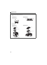
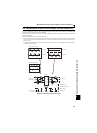
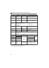
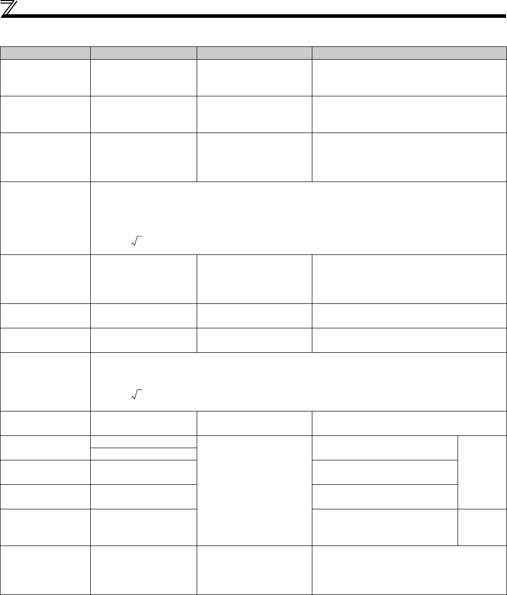
Measurement of main circuit voltages, currents and powers
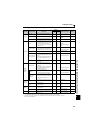
Measuring Points and Instruments
Item Measuring Point Measuring Instrument Remarks (Reference Measured Value)
Power supply voltage
V
1
R/L1-S/L2
S/L2-T/L3
T/L3-R/L1 ∗4
Moving-iron type AC
voltmeter
Commercial power supply
Within permissible AC voltage fluctuation (Refer to
page 278)
Power supply side
current
I
1
R/L1, S/L2, T/L3 line
current ∗4
Moving-iron type AC
ammeter
Power supply side
power
P
1
R/L1, S/L2, T/L3 and
R/L1-S/L2,
S/L2-T/L3,
T/L3-R/L1 ∗4
Electrodynamic type single-
phase wattmeter
P
1=W11+W12+W13 (3-wattmeter method)
Power supply side
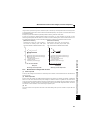
power factor
Pf
1
Calculate after measuring power supply voltage, power
supply side current and power supply side power.
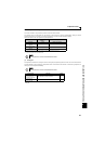
[Three-phase power supply] [Single-phase power supply]
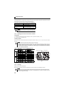
Output side voltage
V
2
Across U-V, V-W and W-U
Rectifier type AC voltage
meter ∗1
(moving-iron type cannot
measure)
Difference between the phases is within 1% of the
maximum output voltage.
Output side current
I
2
U, V and W line currents
Moving-iron type AC
ammeter ∗2
Difference between the phases is 10% or lower of
the rated inverter current.
Output side power
P
2
U, V, W and
U-V, V-W
Electrodynamic type single-
phase wattmeter
P2 = W21 + W22
2-wattmeter method (or 3-wattmeter method)
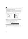
Output side power
factor
Pf
2
Calculate in similar manner to power supply side power factor.
Converter output Across P/+ and N/-
Moving-coil type
(such as tester)
Inverter LED display is lit. 1.35 × V1
Frequency setting
signal
Across 2(+)-5
Moving-coil type
(tester and such may be
used)
(internal resistance 50kΩ or
more)
0 to 10VDC, 4 to 20mADC
"5" is
common.
Across 4(+)-5
Frequency setting
power supply
Across 10(+)-5 5.2VDC
Frequency meter
signal
Across AM(+)-5
Approx. 10VDC at maximum
frequency (without frequency meter)
Start signal
Select signal
Across STF, STR, RH, RM,
RL(+)-SD
When open
20 to 30VDC
ON voltage: 1V or less
"SD" is
common.
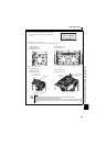
Fault signal
Across A-C
Across B-C
Moving-coil type
(such as tester)
Continuity check ∗3
<Normal><Fault>
Across A-C Discontinuity Continuity
Across B-C Continuity Discontinuity
∗1 Use an FFT to measure the output voltage accurately. An FA tester or general measuring instrument cannot measure accurately.
∗2 When the carrier frequency exceeds 5kHz, do not use this instrument since using it may increase eddy-current losses produced in metal parts inside the
instrument, leading to burnout. In this case, use an approximate-effective value type.
∗3 When the setting of Pr. 192 A,B,C terminal function selection is positive logic
∗4 T/L3 is only for the three-phase power input specification models.
Pf1
P1
3V1 I× 1
------------------------
100×=
%
Pf1
P1
V1 I× 1
----------------
100×=
%
Pf2
P2
3V2 I2×
------------------------
100×=
%