


231
Useful functions
4
PARAMETERS
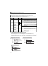
(4) Main circuit capacitor life display (Pr. 258, Pr. 259)
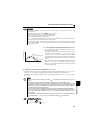
The deterioration degree of the control circuit capacitor is displayed in Pr. 258 as a life.
On the assumption that the main circuit capacitor capacitance at factory shipment is 100%, the capacitor life is displayed
in Pr. 258 every time measurement is made.
When the measured value falls to or below 85%, Pr. 255 bit 1 is turned on and also an alarm is output to the Y90 signal.
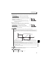
Measure the capacitor capacity according to the following procedure and check the deterioration level of the capacitor
capacity.
1) Check that the motor is connected and at a stop.
2) Set "1" (measuring start) in Pr. 259.
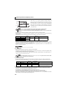
3) Switch power off. The inverter applies DC voltage to the motor to measure the capacitor capacity while the inverter is
off.
4) After confirming that the LED of the operation panel is off, power on again.
5) Check that "3" (measuring completion) is set in Pr. 259, read Pr. 258, and check the deterioration degree of the main
circuit capacitor.
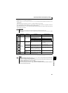
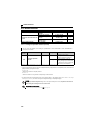
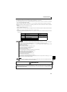
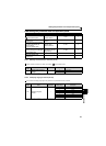
Pr. 259 Description Remarks
0
No measurement Initial value
1
Measurement start
Measurement starts when the
power supply is switched off.
2
During measurement
Only displayed and cannot be
set
3
Measurement complete
8
Forced end
9
Measurement error
REMARKS
When the main circuit capacitor life is measured under the following conditions, "forced end" (Pr. 259 = "8") or "measuring error"
(Pr. 259 ="9") occurs or it remains in "measuring start" (Pr. 259 = "1"). Therefore, do not measure in such case.
In addition, even when "measurement completion" (Pr. 259 = "3") is confirmed under the following conditions, normal
measurement can not be done.
(a) FR-HC or FR-CV is connected.
(b) DC power supply is connected to the terminal P/+ and N/-.
(c) The power supply switched on during measurement.
(d) The motor is not connected to the inverter.
(e) The motor is running (coasting)
(f) The motor capacity is two rank smaller as compared to the inverter capacity.
(g) The inverter is tripped or a fault occurred when power is off.
(h) The inverter output is shut off with the MRS signal.
(i) The start command is given while measuring.
(j) The parameter unit (FR-PU04/FR-PU07) is connected.
(k) Use terminal PC as power supply.
(l) I/O terminal of the control terminal block is on (continuity).
Turning the power on during measuring before LED of the operation panel turns off, it may remain in "measuring" (Pr. 259 = "2")
status. In such case, carry out operation from step 2.
POINT
For the accurate life measuring of the main circuit capacitor, perform after more than 3 hrs passed since the turn
off of the power as it is affected by the capacitor temperature.
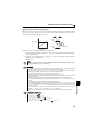
WARNING
When measuring the main circuit capacitor capacity (Pr. 259 Main circuit capacitor life measuring = "1"), the DC
voltage is applied to the motor for 1s at powering off. Never touch the motor terminal, etc. right after powering
off to prevent an electric shock.