


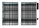
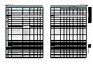
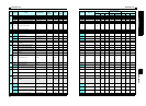
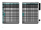
Parameter listParameter list
68
4
PARAMETERS
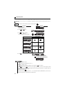
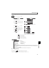
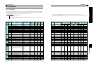
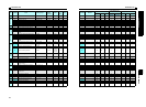
Parameter List
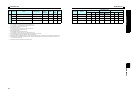
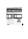
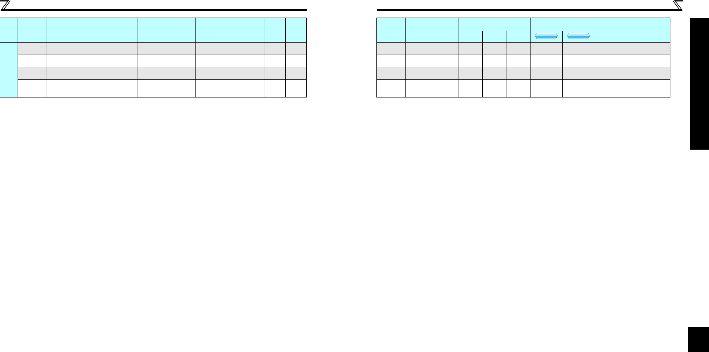
Clear parameters
Initial value change list
Pr.CL Parameter clear 0, 1 1 0 242 Pr.CL — — — — — — — —
ALLC All parameter clear 0, 1 1 0 242 ALLC ——— — — — — —
Er.CL Faults history clear 0, 1 1 0 244 Er.CL — — — — — — — —
Pr.CH Initial value change list — — — 243 Pr.CH ——— — — — — —
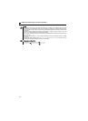
∗1 Differ according to capacities.
6%: FR-D720-042 or less, FR-D740-022 or less, FR-D720S-042 or less
4%: FR-D720-070 to 165, FR-D740-036 to 080, FR-D720S-070 and 100
3%: FR-D720-238 and 318, FR-D740-120 and 160
∗2 Differ according to capacities.
5s: FR-D720-165 or less, FR-D740-080 or less, FR-D720S-008 to 100
10s: FR-D720-238 and 318, FR-D740-120 and 160
∗3 Differ according to capacities.
6%: FR-D720-008 and 014, FR-D720S-008 and 014
4%: FR-D720-025 or more, FR-D740-012 or more, FR-D720S-025 or more
∗4 Write is disabled in the communication mode (network operation mode) from the PU connector.
∗5 The initial value differs according to the voltage class. (200V class, 400V class)
∗6 The parameter number in parentheses is the one for use with the operation panel (PA02) for the FR-E500 series or parameter unit (FR-PU04/FR-PU07).
∗7 These parameters are communication parameters that are not cleared when parameter clear (all clear) is executed from RS-485 communication. (Refer to
page 180 for RS-485 communication)
∗8 Available only for the three-phase power input specification model.
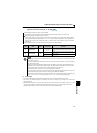
Func-
tion
Parameter
Name Setting Range
Minimum
Setting
Increments
Initial
Value
Refer
to
Page
Customer
Setting
Parameter
Remarks
Instruction Code
Control Mode-based
Correspondence Table
Parameter
Read Write
Extended
Copy Clear
All clear
V/F
V/F
V/F
GP
MFVC
GP
MFVC
GP
MFVC