


93
Frequency setting by external terminals
4
PARAMETERS
4.6.3 Remote setting function (Pr. 59)
The above parameter can be set when Pr. 160 Extended function display selection = "0". (Refer to page 156)
* External running frequency (other than multi-speed) or PU running frequency
NOTE
When Pr. 29 Acceleration/deceleration pattern selection = "1" (S-pattern acceleration/deceleration A), the acceleration/
deceleration time is the period of time required to reach Pr. 3 Base frequency.
The Pr. 15 setting should be equal to or higher than the Pr. 13 Starting frequency.
The JOG signal can be assigned to the input terminal using any of Pr. 178 to Pr. 182 (input terminal function selection).
When terminal assignment is changed, the other functions may be affected. Please make setting after confirming the
function of each terminal.
During Jog operation, the second acceleration/deceleration via the RT signal cannot be selected. (The other second
functions are valid. (Refer to page 227))
When Pr. 79 Operation mode selection = "4", pressing of the operation panel and
/ of the parameter unit
(FR-PU04/FR-PU07) starts the inverter and pressing stops the inverter.
This function is invalid when Pr. 79 = "3".
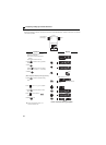
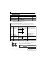
Parameters referred to
Pr. 13 Starting frequency Refer to page 98
Pr. 29 Acceleration/deceleration pattern selection Refer to page 99
Pr. 20 Acceleration/deceleration reference frequency, Pr. 21 Acceleration/deceleration time increments Refer to page 96
Pr. 79 Operation mode selection Refer to page 165
Pr. 178 to Pr. 182 (input terminal function selection) Refer to page 113
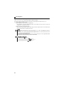
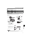
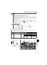
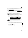
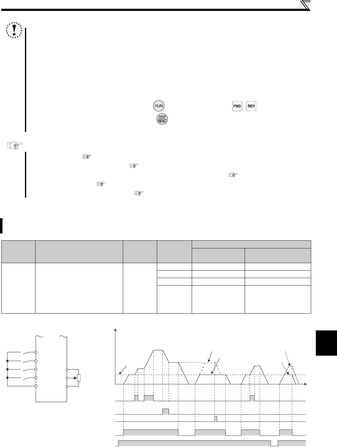
Even if the operation panel is located away from the enclosure, you can use contact signals to perform continuous
variable-speed operation, without using analog signals.
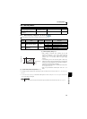
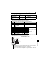
Parameter
Number
Name Initial Value
Setting
Range
Description
RH, RM, RL signal
function
Frequency setting
storage function
59
Remote function selection
0
0 Multi-speed setting —
1 Remote setting With
2 Remote setting Not used
3 Remote setting
Not used
(Turning STF/STR off
clears remotely-set
frequency.)
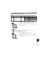
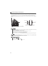
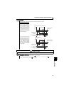
Forward rotation
Acceleration
Deceleration
Clear
Inverter
Connection diagram
for remote setting
STF
RH
RM
RL
SD
10
2
5
0
ON
ON
ON
ON
ON
ON
ON
ON
ON
ON ON
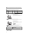
Deceleration
(RM)
Clear (RL)
Acceleration
(RH)
Forward rotation
(STF)
Power supply
0Hz
Time
Output frequency (Hz)
*
When Pr. 59 = 1
When Pr. 59 = 2, 3
When Pr. 59 = 1, 2
When Pr. 59 = 3