


I
1 OUTLINE 1
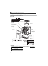
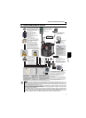
1.1 Product checking and parts identification......................................... 2
1.2 Inverter and peripheral devices.......................................................... 3
1.2.1 Peripheral devices .......................................................................................................................... 4
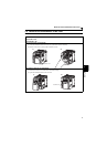
1.3 Removal and reinstallation of the cover ............................................ 5
1.3.1 Front cover...................................................................................................................................... 5
1.3.2 Wiring cover.................................................................................................................................... 7
1.4 Installation of the inverter and enclosure design.............................. 8
1.4.1 Inverter installation environment..................................................................................................... 8
1.4.2 Cooling system types for inverter enclosure................................................................................. 10
1.4.3 Inverter placement........................................................................................................................ 11
2 WIRING 13
2.1 Wiring................................................................................................. 14
2.1.1 Terminal connection diagram ....................................................................................................... 14
2.2 Main circuit terminal specifications................................................. 15
2.2.1 Specification of main circuit terminal ............................................................................................ 15
2.2.2 Terminal arrangement of the main circuit terminal, power supply and the motor wiring............... 15
2.2.3 Cables and wiring length .............................................................................................................. 17
2.3 Control circuit specifications ........................................................... 20
2.3.1 Control circuit terminal.................................................................................................................. 20
2.3.2 Changing the control logic ............................................................................................................ 22
2.3.3 Wiring of control circuit ................................................................................................................. 24
2.3.4 Wiring instructions ........................................................................................................................ 28
2.3.5 Connection to the PU connector................................................................................................... 29
2.4 Connection of stand-alone option unit ............................................. 31
2.4.1 Connection of a dedicated external brake resistor (MRS type, MYS type, FR-ABR)
(FR-D720-025 or more, FR-D740-012 or more, FR-D720S-025 or more) ................................... 31
2.4.2 Connection of the brake unit (FR-BU2) ........................................................................................ 33
2.4.3 Connection of the high power factor converter (FR-HC) .............................................................. 34
2.4.4 Connection of the power regeneration common converter (FR-CV) ............................................ 35
2.4.5 Connection of a DC reactor (FR-HEL).......................................................................................... 35
3 PRECAUTIONS FOR USE OF THE INVERTER 37
3.1 EMC and leakage currents................................................................ 38
CONTENTS