


252
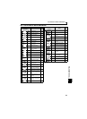
Causes and corrective actions
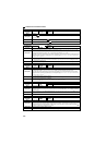
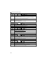
Operation panel
indication
PS
FR-PU04
FR-PU07
PS
Name
PU stop
Description
Stop with of the PU is set in Pr. 75 Reset selection/disconnected PU detection/PU stop selection. (For Pr. 75 refer to
page 158 .)
Check point
Check for a stop made by pressing of the operation panel.
Corrective action
Turn the start signal off and release with .
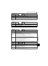
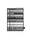
Operation panel
indication
RB
FR-PU04
FR-PU07
RB
Name
Regenerative brake prealarm
Description
Appears if the regenerative brake duty reaches or exceeds 85% of the Pr. 70 Special regenerative brake duty value.
When the setting of Pr. 70 Special regenerative brake duty is the initial value (Pr. 70 = "0"), this warning does not occur. If
the regenerative brake duty reaches 100%, a regenerative overvoltage (E. OV_) occurs.
The RBP signal can be simultaneously output with the [RB] display. For the terminal used for the RBP signal output,
assign the function by setting "7 (positive logic) or 107 (negative logic)" in Pr. 190 or Pr. 192 (output terminal function
selection). (Refer to page 119).
Check point
1. Check that the brake resistor duty is not high.
2. Check that the Pr. 30 Regenerative function selection and Pr. 70 Special regenerative brake duty settings are correct.
Corrective action
1. Increase the deceleration time.
2. Check that the Pr. 30 Regenerative function selection and Pr. 70 Special regenerative brake duty settings.
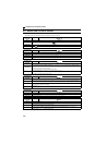
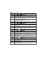
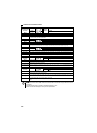
Operation panel
indication
TH
FR-PU04
FR-PU07
TH
Name
Electronic thermal relay function prealarm
Description
Appears if the cumulative value of the Pr. 9 Electronic thermal O/L relay reaches or exceeds 85% of the preset level. If
it reaches 100% of the Pr. 9 Electronic thermal O/L relay setting, a motor overload trip (E. THM) occurs.
The THP signal can be simultaneously output with the [TH] display. For the terminal used for THP signal output,
assign the function by setting "8 (positive logic) or 108 (negative logic)" in Pr. 190 or Pr. 192 (output terminal function
selection). (Refer to page 119).
Check point
1. Check for large load or sudden acceleration.
2. Is the Pr. 9 Electronic thermal O/L relay setting is appropriate? (Refer to page 100)
Corrective action
1. Reduce the load and frequency of operation.
2. Set an appropriate value in Pr. 9 Electronic thermal O/L relay. (Refer to page 100)
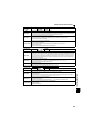
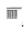
Operation panel
indication
MT
FR-PU04 ——
FR-PU07 MT
Name
Maintenance signal output
Description
Indicates that the cumulative energization time of the inverter has reached a given time.
When the setting of Pr. 504 Maintenance timer alarm output set time is the initial value (Pr. 504 = "9999"), this warning
does not occur.
Check point
The Pr. 503 Maintenance timer setting is larger than the Pr. 504 Maintenance timer alarm output set time setting. (Refer to
page 233).
Corrective action
Setting "0" in Pr. 503 Maintenance timer erases the signal.
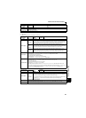
Operation panel
indication
UV
FR-PU04
FR-PU07
——
Name
Undervoltage
Description
If the power supply voltage of the inverter decreases, the control circuit will not perform normal functions. In addition,
the motor torque will be insufficient and/or heat generation will increase. To prevent this, if the power supply voltage
decreases below about 115VAC (230VAC for 400V class), this function stops the inverter output and displays .
An alarm is reset when the voltage returns to normal.
Check point
Check that the power supply voltage is normal.
Corrective action
Check the power supply system equipment such as power supply.